BuGlessRB,
Thanks so much for sharing this. I spent some time fooling around with various free CAD programs but didn't get as far as making models. I hope this works out for you; please report back with your progress.
Another fun small driver to print enclosures for might be the Dayton ND91 or ND65. As X has pointed out though, making halves is probably the key to printing larger enclosures.
What are the max dimensions of your model so we know if it will fit on our printer beds? One way to keep part size down is to make two halves inter-locking petals of a flower like.
Thanks.
The max width and length are slightly below 280mm each.
The max height is slightly below 180mm.
So I guess that just about fits most 3-D printers.
The only remaining reason to print it as two interconnecting halves would be price.
If you let someone print it, printing it as two halves allows you to get all components for a seven-speaker system using merely two printing sessions.
Since I want to have nine of these speakers (seven for my home cinema system, and two extra to experiment with), it starts to become profitable to buy a 3-D printer specifically to create the speakers; it's probably cheaper than paying some service to print them for me.
This model was the result of fooling around about two hours with OpenSCAD (never used OpenSCAD before, and I'm definitely not an experienced CAD user).
Yeah, as much fun as it is to watch paint dry, that's a long time to wait. Luckily, this is a second pair that I made since the parts were basically half price with double the quantity. So, I'm not without speakers in the meantime...
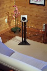
Beautiful finish those new pair of Hypercubes.
Praise to gmad and wesayso that whatever is shared from handmade home build hardware or measured performance its very inspiring and over normal average in quality, thanks for that.
By the way gmad, have you tried trial version of APL_TDA measurement suite.
Praise to gmad and wesayso that whatever is shared from handmade home build hardware or measured performance its very inspiring and over normal average in quality, thanks for that.
By the way gmad, have you tried trial version of APL_TDA measurement suite.
Thanks for the kind words BYRTT, I guess we just can't help ourselves... it isn't all that easy to please yourself if you're wired this way  .
.
Gmad, I'd love to see some results from you using the APL_TDA measurement suite too! Just to see what this near field setup is doing at the listening position.
Curious about how that looks, both the signal and room influences on the graph. I wonder if the room part might even be cleaner than I can get it due to you listening up close (compared to me) and away from boundaries (also compared to me)...
Your virtual recordings did sound quite convincing, let us see how that looks in a TDA graph 🙂.
.Gmad, I'd love to see some results from you using the APL_TDA measurement suite too! Just to see what this near field setup is doing at the listening position.
Curious about how that looks, both the signal and room influences on the graph. I wonder if the room part might even be cleaner than I can get it due to you listening up close (compared to me) and away from boundaries (also compared to me)...
Your virtual recordings did sound quite convincing, let us see how that looks in a TDA graph 🙂.
Thanks so much, BYRTT, and thanks to both of you for the overall support. I'll be happy to try to provide any measurements you'd like to see. I haven't looked at that software yet so I don't know what's involved exactly. I don't think I'm able to implement wesayso's method of applying convolution to the measurement signal; I'll have to look into that.
Also, I'll need a little time to get settled back in. I thought something was different (off?) about the sound last night while listening briefly with one of the drivers in its new enclosure and the other still in its original enclosure. I'll need to investigate that...
Also, I'll need a little time to get settled back in. I thought something was different (off?) about the sound last night while listening briefly with one of the drivers in its new enclosure and the other still in its original enclosure. I'll need to investigate that...
First get it back to how it's supposed to be 🙂. But if you want to try the TDA software you could do the convolution with a 30 day trail version of JRiver. It has a WDM driver that you can use to route everything trough JRiver. And if that doesn't work out there is another way in JRiver to do more or less the same. Be prepared though, I couldn't say goodbye to JRiver after trying it for 30 days.
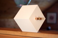
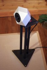
Ok, it's all good. I have both speakers playing in the finished enclosures and it sounds good. I'm really not sure what I was hearing (if anything at all) last night with one enclosure swapped. Maybe filter tasting and wine tasting on the same night was too much. Attached a couple of views of the left speaker...
Attachments
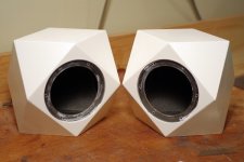
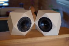
I'd be inclined to think that the merits of the design has much to do with the approximation of the shape to a sphere on the outside (diffraction) and the reduction of the problems of a real sphere on the inside (clean resonance). Also structurally, the shape is sound (no pun intended) because all the corners makes it strong and non-resonant.
It's hardly necessary to embarrass oneself with speculation of pyramid energy or the like to explain why this works.
Very interesting and good looking speaker. Do you have plans with the cut angles to give out Gmad?
It's hardly necessary to embarrass oneself with speculation of pyramid energy or the like to explain why this works.
Very interesting and good looking speaker. Do you have plans with the cut angles to give out Gmad?
Thanks, Squeak.
I think you have made some very good points. I do think the diffraction characteristics are at least largely responsible for the pleasant sound at the sides/rear of the enclosure as well as the great disappearing act the speaker seems to perform. And yes, the enclosure is very stiff and strong despite being only 6mm thick which as we know has obvious benefits.
As for the internal geometry, I personally still find this part fascinating. It seems like there are two ways to look at this shape. Whereas a cube can be thought of as having 3 pairs of opposing square faces, the RD can be thought of as having 6 pairs of opposing rhombic faces or 3 pairs of opposing "pyramidal faces". Having pairs of opposing surfaces* which are both parallel and equidistant does not seem like a good characteristic for a speaker enclosure but maybe having opposing pyramids is?
So, the question I like to ask is which way does the internal geometry appear to the expanding wavefront launched from the rear of the driver? I can't say for sure, but I can tell you that there is very little difference in performance between the empty vs. stuffed enclosure which is not what I would have expected with a shape that seems to be somewhere between a cube and a sphere.
Anyway, I hear what you're saying regarding speculation and far-out explanations, and I do appreciate your input here. I am no physicist or mathematician. I have an active imagination combined with a somewhat "open mind" and I must admit that this shape has captured my imagination. I also admit that I like to think that there is something special about this shape. However, I remain very much open to considering anyone's clear and "conventional" explanation for my findings. I'm looking for the truth and I do hope for this discussion to continue in a positive and productive manner.
As I recall, Mudjester kindly provided some drawings at some point. Basically, the shape we want is a rhombus where the ratio of the minor axis to the major axis is 1 : 1.414 and the edges are beveled at 60 deg. In my CAD software, I draw a "plus sign" where the horizontal line is "L" and the vertical line is L x 1.414 (extending up and down a distance of L x 0.707 from the mid-point), and then I just connect the ends of the lines (it looks like a kite until I erase the interior lines). If we could cut two of these pieces in half without any loss due to blade width (laser cutting?) we would have the triangular pieces needed to connect the baffle (L x L with 45 deg beveled edges) to the remaining 8 rhombi.
Unfortunately, this is not an easy enclosure for anyone to make. However, I believe in this design and although I have been extremely busy this past year (for a very good reason 🙂), I still plan in the not-too-distant future to purchase a high-end saw and have a couple of precision machined aluminum pieces made to calibrate the miter gauge and blade tilt positions for cutting these pieces. Maybe I could put together some flat packs eventually.
-Greg
*I realize now after having re-read much of this thread (it was moving quickly at the time) that some people have stated that there may be benefits with this shape due to a lack of parallel surfaces, but in fact the opposite is true (it's a tricky shape to make sense of at first).
Last edited:
I agree with Squeak. From the beginning of this thread I was thinking the same thing. I've made some small speakers before with near half spherical front baffles, and the imaging is really nice. I've used those to show people what I'm always ranting about with speakers. It's why I've been interested in these. It's just with two small children at home with a working wife, I have no time to build anything to hear how great they are.
I can re-post the simple drawings if you like. It has all the angles and everything. I'm also happy to post models for printing if anyone wants. I have professional CAD tools and 15 years experience, so I can do pretty much anything anyone wants.
Gmad, if you need help designing your tools, let me know. I'd be happy to draw up whatever you need. I've been collecting the tools I thought I would need to build one. A digital angle gage to set the angle of my table saw, and a precision miter to get .1° accuracy on my cuts. Bought them both from Amazon. But it would be so much nicer to have custom tooling.
MuddJester, thanks for joining in. I guess it's been so long that I forgot how to spell your name in my previous post (apologies for that). You were very generous as I remember and that has not changed. Thanks once again for your offers.
I think I know the miter gauge you're talking about (I'm considering it myself if it's the same one). I just feel like custom calibration tools would make for a more "pure" approach. Also, it seems aluminum can be machined with great precision (tight tolerance).
Let's keep each other updated...
I think I know the miter gauge you're talking about (I'm considering it myself if it's the same one). I just feel like custom calibration tools would make for a more "pure" approach. Also, it seems aluminum can be machined with great precision (tight tolerance).
Let's keep each other updated...
Yeah, took a little break. Just had a second kid so I've been busy.
You're right that it can be machined with tight tolerances, but part of the art is knowing how tight you need them and how tight you can make them without driving up the price. I can help with that.
I have the Kreg miter. A friend at work that has the Incra. You have to get the high end Incra for fractions of an angle control. I don't know if you need fractional control for these speakers. I guess it just depends on the gap size you can tolerate.
Well, I guess you're twice as busy as me then 🙂.
I was thinking of the Incra actually, but it's good that there are choices there. The reason I mentioned aluminum is because I'm considering it as a material for custom "calibration tools". I can request parts with a tolerance of +/- 0.12mm.
I have also considered aluminum for the enclosures but not as something I could produce myself. However, it's not cheap having parts machined for you. I just like the idea of something going together perfectly with no need for any filing/sanding of the edges. And imagine the stiffness of an aluminum hypercube speaker (could you model that? 🙂).
Anyway, all things considered, BB ply on a finely calibrated table seems like a nice way to go...
- Status
- Not open for further replies.
- Home
- Loudspeakers
- Full Range
- Hypercube Loudspeakers