Last I checked a box doesn't have a Q?
An alignment has a Q, it is a mechanical high-pass filter.
Vented boxes does have QL - in parallel with Qe and Qm. Nothing new here, of course.
Joe, if you really ask us all, then I must insist.[...]
So can we have this? Yes?
Me and those who do not have USHER S520 will need the TS+electrical parameters (Z-characteristic of each drive included) in order to follow-correct-help or even use/learn outside of Usher's S520. In so far, it is already Page27 and these numbers are still delayed, when their place is in Page 1.
How about we start from this point - Upload? Is it possible? Yes?
I am sure it will be too hard for me to understand if you say they are irrelevant, or to believe that you don't know them, or to delay again, or even that is too much time-demanding to upload (would take anything like 3minute to attach).
Respect is a two way proposition.
My respects,
Ionmw
Last edited:
Hi Joe,
There is never any problem with you starting a thread and continuing along a reasonable line. Just start the thread.
-Chris
There is never any problem with you starting a thread and continuing along a reasonable line. Just start the thread.
-Chris
You are a bit confused.An alignment has a Q, it is a mechanical high-pass filter.
Vented boxes does have QL - in parallel with Qe and Qm. Nothing new here, of course.
Only a storage of energy has Q, by definition. For EE the simplest form defined at critical coupling is Q=f0/BW.
I would not agree to say that a HP filter has a Q at all, but is sometimes accepted to say Q=1. Now, a Q=0.7 for high-pass(!)... what exactly it means? That it is a lossy filter, be it either shunt or series ?
If you use Q with non-standard meanings (textbook wise) it is OK but you must attach the definition that you use, which is not complicated...
The more exact your description of all terms that you use is, the more effective and productive this discussion will be.
Last edited:
Hi Ionmw,
All filters have a "Q" value. Related to damping. Q=0.7071 would define a butterworth response.
For EE, study filters and especially loudspeaker systems.
-Chris
All filters have a "Q" value. Related to damping. Q=0.7071 would define a butterworth response.
For EE, study filters and especially loudspeaker systems.
-Chris
I would not agree to say that a HP filter has a Q at all
It's generally understood that replacing s with 1/s in a low pass Butterworth transfer function results in a high pass Butterworth.
I would not agree to say that a HP filter has a Q at all, If you use Q with non-standard meanings (textbook wise)
it is OK but you must attach the definition that you use, which is not complicated...
This should keep you out of trouble for a while.
http://www.analog.com/library/analogDialogue/archives/43-09/EDCh 8 filter.pdf?doc=ADA4666-2.pdf
Hi Ionmw,
All filters have a "Q" value. Related to damping. Q=0.7071 would define a butterworth response.
For EE, study filters and especially loudspeaker systems.
-Chris
Thanks Chris.
This sort of thing can derail the discussion. You end up with a heated discussion about whether this or that exists.
Ionmw is OK. Got nothing against him. But there have to be a framework if we are to have this discussion.
I need to take this very slow. Or I know what will happen. So I have to stay focused. But I do believe I have something interesting to bring to the table.
It will be more engineering rather theoretical. Like Kindhornman said to John Kreskovski "Don't ask me to put up the math such as you do, I only understand it intellectually."
I am not saying no maths, I did OK in maths. But rather solution based, engineering based.
Hi Joe,
Kick off your thread by stating it's intent and scope. You can attempt some rules of engagement, but then everyone needs to abide. There are also the forum rules that must be adhered to as well.
Let's have a calm thread for a change.
-Chris
Kick off your thread by stating it's intent and scope. You can attempt some rules of engagement, but then everyone needs to abide. There are also the forum rules that must be adhered to as well.
Let's have a calm thread for a change.
-Chris
You are a bit confused.
Hi Ionmw
You are welcome to come along, we have discussed things before and in a good spirit.
But on this I have not been confused for fourty odd years, honestly. 🙂
Hi Joe,
Kick off your thread by stating it's intent and scope. You can attempt some rules of engagement, but then everyone needs to abide. There are also the forum rules that must be adhered to as well.
Let's have a calm thread for a change.
-Chris
Your words are music to my ears.
At this stage I am waiting for Steve, system7, to make an appearance.
Joe,
Go ahead, I think most of us are with you at this point. One step at a time and we'll work our way through your thought process. I want to see where this leads, I have nothing against the subject and I assume your heading down the current drive road eventually. I was just questioning Esa and what he expected us to do with a common dynamic driver, no servos and no secondary voicecoil. I never got my answers from his book. I didn't do to bad with mathematics myself, just never had it in regards to electronics besides some trig functions and phase angle.
Go ahead, I think most of us are with you at this point. One step at a time and we'll work our way through your thought process. I want to see where this leads, I have nothing against the subject and I assume your heading down the current drive road eventually. I was just questioning Esa and what he expected us to do with a common dynamic driver, no servos and no secondary voicecoil. I never got my answers from his book. I didn't do to bad with mathematics myself, just never had it in regards to electronics besides some trig functions and phase angle.
Is there going to be a new thread as Chris has just suggested or will it remain here under this title?
Is there going to be a new thread as Chris has just suggested or will it remain here under this title?
No, I think I understood Chris right, and it won't be off topic as we eventually will come back to that alternative crossover for the Usher S520. It will all come together then.
Anyone who doesn't understand closed box calculations, please leave the room now!
No, they can stay. 🙂
As I said in the PM to you, we are looking at controlling losses and whether losses due to series elements can be compensated by parallel elements. That's an appetiser.
Please note that 'losses' is defined here as anything that disturbs the alignment, the chosen Q.
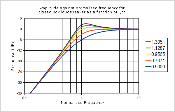
Take the graph you just posted above, let's take Q = 0.7071 (we will shortened it to 0.707), which is maximally flat, that is there is no 'peak' where a peak is defined as the response going up before down. With Q above 0.707 there will be a peak and below or <= 0.707 there will not.
So, I want the Red One!
Again, as your graph above shows, nothing "new" here.
OK, we find ourselves a nice 8" driver in our fertile mind, a basic thought experiment that can easily be realised in the natural world. We measure the T-S Parameters and we find that the driver lends itself to a sealed box and we decide to choose Q=0.707 which I likely would.
There is only one box parameter to decide/calculate, Vb, the volume. In a sealed box, that is the only variable available to us and we can soon hone in on the correct box size.
Let's say it happens to be exactly 50 Litres, and we get:
Qt = 0.707
Fb = 40 Hertz and -3dB an Fb 40 Hertz, and down -12dB @ 20 Hertz.
I think this alignment, all other things considered, is actually very good. With a good driver, in a good room and we will be nears flat around 30 Hertz. But let us ignore room response for now.
The point is that the above chosen alignment, now we have locked in VB, all depends on what?
Any series elements losses.
OK, open discussion, what are these?
 Cut to the chase, Gentlemen. Enough finger pointing and personal remarks.
State your case. Respond to technical questions.
Once more and a thread has had to cleaned and penalties handed down. I suggest you all heed the previous moderation directives already stated above.
Why not start this again?
1. What drivers are you using?
2. Please give us the parameters/measurements for these drivers.
3. Take us through each step of your design process.
Remember that a good teacher will be understood by all and you lost me at the beginning of #274
Is the box volume a series or a parallel element?
1. What drivers are you using?
2. Please give us the parameters/measurements for these drivers.
3. Take us through each step of your design process.
Remember that a good teacher will be understood by all and you lost me at the beginning of #274
Is the box volume a series or a parallel element?
1. What drivers are you using?
2. Please give us the parameters/measurements for these drivers.
3. Take us through each step of your design process.
Hi Mark
Just about going to bed. We keep funny hours down here, you know. 🙂
Not exactly a real driver yet, but we will likely come to that. For now more like a thought experiment that we can manipulate in many dimensions. As this is an Usher S520 thread, so that is actually the design we will come back to.
The Ushers are vented, but to illustrate the thinking about what system7 has called 'the flattening of the impedance,' whether that is only some nice looking trick, or is there actually any benefits behind it, is best analysed using a sealed box. Then move on from there.
Off to bed.
If you are going to discuss damping it's important to understand the difference between the driver alone and the "system". The system consists of the driver, the enclosure, any network between the driver's terminals and the power source (amp), and any preprocessing of the input before the amp. We can always write the simple equation of motion for the driver as
F = ma + bv + kx
where m is moving mass, b is mechanical damping and k is the inverse of the compliance. The difference between a naked driver and one in a box is reflected in k due to the change in compliance when the driver is placed in a sealed box. (It gets more complex for a ported box).
The issue here is the applied force, F. Regardless of the type of source or any network between source and driver terminals we can always express the force as
BL * I = BL * V/Z where V is the voltage applied across the driver's terminals and Z is the driver's impedance. Notice that when expressed this way the back EMF is not present in the equation of motion as it's effects are reflects in Z.
In the simplest case of a series resistance, Rs, the voltage across the terminals is
V = Vs / (1 + Rs/Z)
When Rs = 0, V= Vs and the driver/box system responds as we usually expect. However, when Rs is significant relative to Z, we find that were Z is small V will be somewhat less that Vs. Where Z is larger, around resonance, V will be greater. Thus V will have a peak around resonance. In fact, Rs in series with Z functions as a passive, Q boost filter, providing high voltage across the driver terminal around resonance, thus a greater driving force. It is not so much that the presence of Rs changes the driver's Q but rather that greater force is applied to the driver around resonance resulting is a peaking of the response. This is often explained by saying that the series resistance increase the Qes of the driver. However, if Qes changed then the driver's impedance would also have to change and it doesn't What changes is Qes of the "system" consisting of the driver and the series resistance as seen driven by the amplifier output voltage, Vs. To provide evidence of the fact that the driver's parameters don't change, just consider how the driver's impedance is measured and Qms, Qes, and Qts extracted. We put a series resistance between the driver and the source and measure the voltages on each side of the resistor. It's the same voltage divider as expressed above. With a little rearrangement
Z = Rs/(Vs/V - 1)
I think we all recognize that when making impedance measurements the results are, for the most part, insensitive to the value of Rs. Going a step further, we also accept that placing any type of network between the source and the driver, or driver/box system, has no effect on the Z of the driver, driver/box system. What it does is alter the voltage applied across the driver's terminals and in that way alters the force applied to the driver, hence the driver's response.
Looking at a current source, it is often stated that a current source eliminates electromagnetic damping. Yes and no, but it doesn't change the driver's Q. Again, if Qts would changed, since Qts is related to the driver's Z, Z would have to change, and it does not. What changes is that with a constant current the force changes. This is obvious if you consider the voltage across the driver's terminals when connected to a current source. V = I*Z. Thus, around resonance V must follow Z with a large peak compared to being constant as when connected to a constant voltage source. The current source is, again, equivalent to having a Q boost filter tuned to the resonant frequency.
It all comes down to force. And force comes down to voltage across or current through the driver's VC with impedance Z. What you place between the amp and the driver controls that. And it must be recalled that regardless of the type source, or the network between the source and driver, there is always the back emf generated in the motor and this back emf contributes to resisting current flow.
Last edited:
- Status
- Not open for further replies.
- Home
- Loudspeakers
- Multi-Way
- Joe Rasmussen Usher S520 "Current Compatible" Crossover