but in the ideal case when you place a conjugate network across a driver or a complete speaker, as far as the driver/speaker is concerned, it might as well be connected to a voltage source.
Anyway, that's my very simplistic view.
As far as I am concerned John this is spot on.
Jan
John K,
thank you for that real explanation, I do understand what you are saying. It was definitely thorough enough an explanation to show the differences between driving with voltage and current.
thank you for that real explanation, I do understand what you are saying. It was definitely thorough enough an explanation to show the differences between driving with voltage and current.
Flippin 'eck, voltage and current equivalents aren't hard.
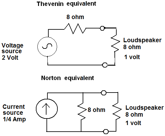
A picture worth a thousand words. 😀
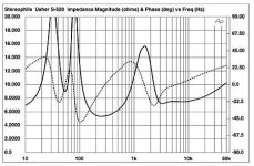
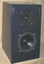
I was struck by Joe Rasmussen's "House Style". Here the Usher and the Elsinore (without impedance correction). 😎
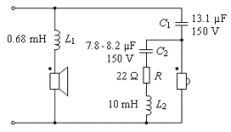
I've drawn up his Usher remodel with values. That 18mH has me scratching my head, but I'll trust Joe on this.
A picture worth a thousand words. 😀
I was struck by Joe Rasmussen's "House Style". Here the Usher and the Elsinore (without impedance correction). 😎
I've drawn up his Usher remodel with values. That 18mH has me scratching my head, but I'll trust Joe on this.
Attachments
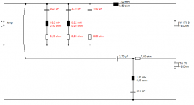
300uF and 18mH acts at 70 Hz on the upper peak of the double peak reflex bass resonance. That just seemed a bit low for a tiny 5" polycone. Which is what was bothering me.System7,
I would assume that 18mH shunt is set for the Fs of the drivers low frequency peak.
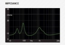
The similar 5" Epos ELS-3 had an upper peak near 100Hz:
Epos ELS-3 loudspeaker Measurements | Stereophile.com
Actually the Usher S520 has a peak near 85Hz, so Joe's circuit looks reasonable. Notches often don't have to hit the exact spot to be most effective. It's always best to model them.
Attachments
Last edited:
System7,
It can be as simple as a difference in mass that is why one speaker of the same size has a very different Fs value. An addition of mass is a simple way to lower the Fs of any speaker.
It can be as simple as a difference in mass that is why one speaker of the same size has a very different Fs value. An addition of mass is a simple way to lower the Fs of any speaker.
3 Notches often don't have to hit the exact spot to be most effective. It's always best to model them.
Indeed. Individual driver parameters can vary as much as 10% between units so it's probably wise not trying to hit a nominal value spot on but having it a bit broader to catch them all.
Jan
Gentlemen,
Actually it is a fairly simple affair to flatten a full range impedance curve: Calsod (now 25+ years old!), and maybe other optimization packages, has a function to linearize Z curves to a desired, pre-defined value.
Take a full range Z measurement, including the system resonant hump, export the .zma file into Calsod, throw in a one or two of roughly calculated LCR shunts and a zobel.
Define the desire target value of the impedance, and let the optimizer run.
Within 5 seconds you end up with a ruler flat 20 Hz 20Khz curve.
Good Luck,
Eelco
Individual driver parameters can vary as much as 10% between units
That would be from a brand that has extremely tight QC. Of the thousands of drivers i have tested i have not seen a large batch test that tight.
From my experience very good QC typically yields < +/- 10%, good as much as +/- 20% and i have seen examples of pairs that are much greater than that.
dave
That would be from a brand that has extremely tight QC. Of the thousands of drivers i have tested i have not seen a large batch test that tight.
From my experience very good QC typically yields < +/- 10%, good as much as +/- 20% and i have seen examples of pairs that are much greater than that.
Ditto. 10% is exceptional for any given parameter. What does seem to be well controlled is the ratio of Qts to fs, so in a sense, it's self-correcting.
Ditto. 10% is exceptional for any given parameter. What does seem to be well controlled is the ratio of Qts to fs, so in a sense, it's self-correcting.
Do you know, would this ratio Qts to Fs have a physical meaning? I don't. Please share to us.
In contrast, the product Qts*Fs would have meaning of "bandwidth" for mechanical-electrical resonance at Fs. Maybe the product is constant?
Heco drivers used in expensive old DUALs like CLxyz, with x>3, y>7and z=0,1,2 appeared to me as within 5%, measured anywhere outside self resonances. Xovers are also <5%. I have compared within originals and also with current new replacements; the tolerance holds.
Hey Joe, cheer up chum!
I've had loads of bans from the illustrious diyaudio! 😀
Usually I spend the ban week doing more productive stuff. 😎
TBH, sometimes I lose it completely against some more critical members. 😱
Let's be honest, you produced a finely crafted couple of posts about impedance equalisation. After all that effort, what was the first response? "Define Noise."
TBH, I'd be tearing my hair out too. 😕
Speakers and amps are hard. So many trade-offs.
I was reading Esa Merilainen recently. Project CS-12 | Current-Drive - The Natural Way of Loudspeaker Operation
It's certainly easier to design speakers with 4 ohm bass. Simpler filters. Hey, I'll stop there. Let's get our breath back. Sometimes you hit the big "So What?" with an idea. Which is hard.
Attachments
That would be from a brand that has extremely tight QC. Of the thousands of drivers i have tested i have not seen a large batch test that tight.
From my experience very good QC typically yields < +/- 10%, good as much as +/- 20% and i have seen examples of pairs that are much greater than that.
dave
OK so I was too optimistic! Good to know.
Jan
Do you know, would this ratio Qts to Fs have a physical meaning? I don't. Please share to us.
Yes. fs/Qts = fc/Qtc. Likewise Vas*fs^2 also tends to be constant from driver to driver. This helps even out unit-to-unit variances in finished systems (assuming the box tolerances are reasonable!).
Yes. fs/Qts = fc/Qtc. Likewise Vas*fs^2 also tends to be constant from driver to driver. This helps even out unit-to-unit variances in finished systems (assuming the box tolerances are reasonable!).
Just like IC's the parameters can't physically be completely independent.
May I have everybody's attention and make a request.
System7 has approached me via PM and based on that, I would like to start a discussion with him rather than secretly via PM, because right now I am wondering whether i can do this on the forum here.
The problem is that it can't just be a single post. It needs to start and then gradually build.
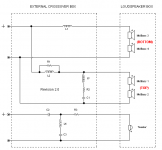
The topic will be about the nature of damping in loudspeakers. I posted this alternative crossover for the Usher S520 and quite happily would have left it at that, made a few basic comments about the thinking behind it - and that would have been fine. Let people build it and hopefully enjoy it, perhaps report back good or bad - whatever. Fine by me.
But now been asked to dig a little deeper and hence this dialogue with system7.
So please, can we have that?
Can we keep the "so what" and "nothing new" type comments at a minimum, as that will not be helpful.
I want to start with a semi-thought experiment, starting with a typical driver, say 8" and suitable for a sealed box of Q = 0.707 and hence the ideal 2nd order Butterworth alignment, maximally flat and -3dB at Fb etc.
Now what can we do to keep that box working at Q = 0.707 and damping staying at that Q, not straying far from it. That will involve the amplifier and potentially other series elements. For example, can the effect of a series element be cancelled out by a parallel element? That is an interesting question.
This could be a starting point and perhaps a little surprise as we look at solutions based on currently known technology and basically applying them, no funny laws or anything.
So can we have this? Yes?
System7 has approached me via PM and based on that, I would like to start a discussion with him rather than secretly via PM, because right now I am wondering whether i can do this on the forum here.
The problem is that it can't just be a single post. It needs to start and then gradually build.
The topic will be about the nature of damping in loudspeakers. I posted this alternative crossover for the Usher S520 and quite happily would have left it at that, made a few basic comments about the thinking behind it - and that would have been fine. Let people build it and hopefully enjoy it, perhaps report back good or bad - whatever. Fine by me.
But now been asked to dig a little deeper and hence this dialogue with system7.
So please, can we have that?
Can we keep the "so what" and "nothing new" type comments at a minimum, as that will not be helpful.
I want to start with a semi-thought experiment, starting with a typical driver, say 8" and suitable for a sealed box of Q = 0.707 and hence the ideal 2nd order Butterworth alignment, maximally flat and -3dB at Fb etc.
Now what can we do to keep that box working at Q = 0.707 and damping staying at that Q, not straying far from it. That will involve the amplifier and potentially other series elements. For example, can the effect of a series element be cancelled out by a parallel element? That is an interesting question.
This could be a starting point and perhaps a little surprise as we look at solutions based on currently known technology and basically applying them, no funny laws or anything.
So can we have this? Yes?
Joe,
can we assume this is a ported box that you are aiming at to have the Q your stating here? And are you choosing the 2nd order filter for a specific reason except for the simplicity of a single series shunt set of elements?
can we assume this is a ported box that you are aiming at to have the Q your stating here? And are you choosing the 2nd order filter for a specific reason except for the simplicity of a single series shunt set of elements?
Joe,
can we assume this is a ported box that you are aiming at to have the Q your stating here?
No, for simplicity's sake, I would start with a sealed box. Then see what we can do to a sealed box, where the Q = 0.707 and what we can do to that.
And are you choosing the 2nd order filter for a specific reason except for the simplicity of a single series shunt set of elements?
I am choosing a 2nd order box alignment (you call it a filter, and it is, a mechanical high-pass filter), a Butterworth alignment, as that simplifies things. Later would have to come back to vented box - you may have noted that the Usher S520 is a vented box - so would eventually need to come back to that.
I want to point out that there will always be compromises, sometimes they can be avoided largely, other times more severely, but still worth it. That is the difference between sealed and vented alignments, and we will have to cover that.
- Status
- Not open for further replies.
- Home
- Loudspeakers
- Multi-Way
- Joe Rasmussen Usher S520 "Current Compatible" Crossover