I first saw it in a schematic of a PA amp from the 40's or 50's that ran a pair of 807's in push pull. Drive fed directly to G2, with a resistor from G2 to G1.
There was mention of "high Mu triode mode" in a data sheet for a transmitting pentode from the WWII era. I believe it had the two grids tied directly together. Can't find in now.
I tried that with a sweep tube and had to pick up parts of exploded mosfet from all over the room......twice!
That's weird since paralleling all the grids of a pentode to make a zero bias "triode" for RF power amplification is quite common.
Did a re-engineering job back in high school for this guy who wanted a high powered CB linear. The original used 4 6KD6 in a SE parallel arrangement that trioded the finals by paralleling the grids and beam formers. It was a GG topology. This design was intended to boost the output of a 30W transceiver.
Since CB rigs put out 5W, this meant a redesign. I kept the GG topology, but went PPP with the finals, and powered the screens for added power sensitivity. He had no trouble being heard after that. 😀 Nothing ever blew up, but then MOSFETs weren't involved, just double tuned, air core, RF xfmrs.
Heh, funny to see that old screen drive thread again, deja vu. OldEurope was trying to solve the same problem. So close even. Wonder if he still tunes in here. Problem finally solved 8 years later.
That previous STC S11E12/CV4060 Amp is running with g1 negative (so not drawing current through the resistor to g1). Then g2 adds some additional gm (Mu 5.5 => 18% from g2) But it ends up sacrificing a potential triode configured Rp for a pentode Rp.
That previous STC S11E12/CV4060 Amp is running with g1 negative (so not drawing current through the resistor to g1). Then g2 adds some additional gm (Mu 5.5 => 18% from g2) But it ends up sacrificing a potential triode configured Rp for a pentode Rp.
Last edited:
I guess there ain't no free lunch... I am not sure what he did exactly, but somehow he got himself banned from all the tube-related forums. But reading some of the old threads, it seems that he did have many interesting ideas though...Heh, funny to see that old screen drive thread again, deja vu. OldEurope was trying to solve the same problem. So close even. Wonder if he still tunes in here. Problem finally solved 8 years later.
That previous STC S11E12/CV4060 Amp is running with g1 negative (so not drawing current through the resistor to g1). Then g2 adds some additional gm (Mu 5.5 => 18% from g2) But it ends up sacrificing a potential triode configured Rp for a pentode Rp.
"seems that he did have many interesting ideas though..."
Indeed, miss the old guy. His ideas definitely got you thinking, even if you didn't agree with them all the time. Totally different perspectives. Plus some oddities, like design rules that forum members supposedly enforced (according to him), which were a bit insulting at times, and then a set of rules that He followed for the golden tube way. Was a bit like a board game where certain moves were legal, and others weren't. Seemed like the bandwidth there stretched from genius to absurdity, a little hard on some members to swallow.
I recall he insisted that a draw-able signal path from input to output was all important, and could not be violated with SS devices, but SS devices not in the serial path were OK. That caused a few arguments about shunt effects and Kirchoff's laws. Well, was easy for anyone to get into arguments with such rigid rules, one of them must have blown up.
Last edited:
"seems that he did have many interesting ideas though..."
Indeed, miss the old guy. His ideas definitely got you thinking, even if you didn't agree with them all the time. Totally different perspectives. Plus some oddities, like design rules that forum members supposedly enforced (according to him), which were a bit insulting at times, and then a set of rules that He followed for the golden tube way. Was a bit like a board game where certain moves were legal, and others weren't. Seemed like the bandwidth there stretched from genius to absurdity, a little hard on some members to swallow.
I recall he insisted that a draw-able signal path from input to output was all important, and could not be violated with SS devices, but SS devices not in the serial path were OK. That caused a few arguments about shunt effects and Kirchoff's laws. Well, was easy for anyone to get into arguments with such rigid rules, one of them must have blown up.
OldEurope had a good point that almost nobody really understood what a Loftin-White design is all about. For innovation We need people that can think "out of the box" like him.
OldEurope had a good point that almost nobody really understood what a Loftin-White design is all about. For innovation We need people that can think "out of the box" like him.
I enjoyed his blog on the Loftin-White and his novel solution for using the triode driver, but more importantly for pointing out the differences between part 1 and part 3 of the design.
Last edited:
Hi!
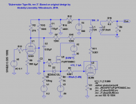
Speaking of "Right handed triode mode", you can do with such a triode the same as with pentode adding a local feedback. Long time ago we discussed the topic on my forum, and Frank (Knarf nickname) simulated an amp and got excellent results. Attaching.
Speaking of "Right handed triode mode", you can do with such a triode the same as with pentode adding a local feedback. Long time ago we discussed the topic on my forum, and Frank (Knarf nickname) simulated an amp and got excellent results. Attaching.
Attachments
Is there any data on the effect of g3 (when available)?
So this is about g2 drive with a resistor divider to g1? Congratulations, you've rediscovered the "linearized JFET" trick...???
Tim
So this is about g2 drive with a resistor divider to g1? Congratulations, you've rediscovered the "linearized JFET" trick...???
Tim
No, it is about all 3 grids together.
Speaking of the 3'Rd grid, I supply it with +12 from filament. As the result I can increase G2 voltage without increasing it's current and get higher current swing on anode in negative G1 drive region.
Speaking of the 3'Rd grid, I supply it with +12 from filament. As the result I can increase G2 voltage without increasing it's current and get higher current swing on anode in negative G1 drive region.
Attachments
No, it is about all 3 grids together.
In one of your old posts from way back, you mentioned a right-handed triode GU-50 amplifier able to produce 200W, would you still have the schematic of such amplifier, or recall what the operating conditions might have been?
TIA,
jaz
If you want g3 effects, here is the thread:
http://www.diyaudio.com/forums/tubes-valves/160240-suppresor-grid-used-feedback.html#post2066795
You will want something like a 6LE8 or 9KC6 if you want g3 to do much though.
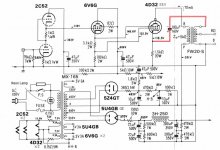
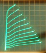
Here (attached below, the g2/g1 driven 4D32 ) is what got the present g2/g1 compensation scheme rolling. AJT posted this in the "Screen driven 6KD6 SE" thread, post 23. (possibly from MJ magazine) It's the only schematic I've seen so far that is doing everything correctly (g2 drive, g1 positive, R from g2 to g1, and R from g1 to cathode). (the CFB included there won't do much this way with a resistive drive to g1 however)
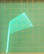
When I tried that setup on a 26LX6, this is what I got (2nd attached pic):
(and it only takes like 50V drive to get 1/2 an Amp out!!)
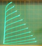
The 3rd attached pic shows the compensation effects of g1 (only) operating this way.
Here is another linearization scheme, the vacuum tube current mirror. Linear current gain. Using the g1 in the positive region will also get you something similar, except the current gain droops off for g1 in that case. (making it useful for the present g2/g1 compensation scheme however)
http://www.diyaudio.com/forums/tubes-valves/40595-long-lost-linear-gain-stage.html
-------------
http://www.diyaudio.com/forums/tubes-valves/160240-suppresor-grid-used-feedback.html#post2066795
You will want something like a 6LE8 or 9KC6 if you want g3 to do much though.
Here (attached below, the g2/g1 driven 4D32 ) is what got the present g2/g1 compensation scheme rolling. AJT posted this in the "Screen driven 6KD6 SE" thread, post 23. (possibly from MJ magazine) It's the only schematic I've seen so far that is doing everything correctly (g2 drive, g1 positive, R from g2 to g1, and R from g1 to cathode). (the CFB included there won't do much this way with a resistive drive to g1 however)
When I tried that setup on a 26LX6, this is what I got (2nd attached pic):
(and it only takes like 50V drive to get 1/2 an Amp out!!)
The 3rd attached pic shows the compensation effects of g1 (only) operating this way.
Here is another linearization scheme, the vacuum tube current mirror. Linear current gain. Using the g1 in the positive region will also get you something similar, except the current gain droops off for g1 in that case. (making it useful for the present g2/g1 compensation scheme however)
http://www.diyaudio.com/forums/tubes-valves/40595-long-lost-linear-gain-stage.html
-------------
Attachments

Last edited:
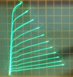
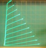
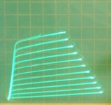
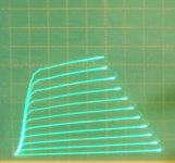
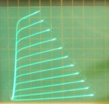
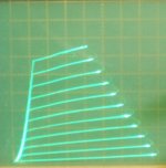
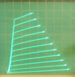
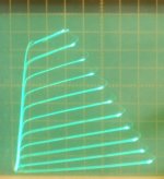
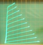
For comparison, 26LX6 in g1 drive, g2 drive and "Crazy Drive" with the drive voltage step sizes.
All 50 mA/div Vert., 50V/div Horiz.
1) g1 1V steps
2) g2 7V steps
3) "Crazy Drive" 5V steps
4) "Crazy Drive" 5.4V steps ( for better comparison with the g2 case)
Crazy Drive is as straight as an arrow. Only below about +1V drive does it start to noticeably compress.
All 50 mA/div Vert., 50V/div Horiz.
1) g1 1V steps
2) g2 7V steps
3) "Crazy Drive" 5V steps
4) "Crazy Drive" 5.4V steps ( for better comparison with the g2 case)
Crazy Drive is as straight as an arrow. Only below about +1V drive does it start to noticeably compress.
Attachments

Last edited:
In one of your old posts from way back, you mentioned a right-handed triode GU-50 amplifier able to produce 200W, would you still have the schematic of such amplifier, or recall what the operating conditions might have been?
TIA,
jaz
AFAIR, 1.2 kV on anode
Here are some more "Crazy Drive" plate curves for more tubes.
All are 50 mA/div Vert., 50V/div Horiz. 7V steps on g2 (down from the max Vg2 listed)
1) 26DQ5 71V Vg2 max., Rg2g1 = 1.89K, Rg1k = 1.1K
2) 24JE6 72V Vg2 max., Rg2g1 = 3.7K, Rg1k = 1.46K
3) 17KV6 75V Vg2 max., Rg2g1 = 2.59K, Rg1k = 775
4) 12GT5 77V Vg2 max., Rg2g1 = 1.94K, Rg1k = 2.7K
5) 22JG6 73V Vg2 max., Rg2g1 = 1.35K, Rg1k = 915
6) 22LU8 76V Vg2 max., Rg2g1 = 1.3K, Rg1k = 574
7)17KV6 g2 drive, 80V VG2 max.
8)26DQ5 conventional g1 drive
Attachments
-
 rsz_17kv6_g2_00_7vs_80v.jpg52.9 KB · Views: 102
 -
 rsz_22lu8_g2_g1_7vs_76v.jpg55.8 KB · Views: 102
 -
 rsz_22jg6_g2_g1_7vs_73v.jpg64.5 KB · Views: 96
 -
 rsz_12gt5_g2_g1_7vs_77v.jpg54.5 KB · Views: 98
 -
 rsz_17kv6_g2_g1_7vs_75v.jpg58.6 KB · Views: 100
 -
 rsz_24je6_g2_g1_7vs_72v.jpg61.2 KB · Views: 113
 -
 rsz_26dq5_g2_g1_7vs_71v.jpg61.7 KB · Views: 94
 -
 rsz_26dq5_p.jpg64.2 KB · Views: 98
26DQ5 71V Vg2 max., Rg2g1 = 1.89K, Rg1k = 1.1K
Hello Smoking-amp, I plugged your Rg2g1 recommendations into my LTspice model for a 6DQ5 PP screen drive amp I have been playing with on my bench. The Rg2g1 values model very well in my simulations. I will have to install the resistor divider and try the Rg2g1 drive on the bench in the days to come when I have some spare time to hobby. I have enjoyed your "Crazy Drive" very much.....Thanks for all the curve tracing on screen drive and Crazy Drive. Mickeystan
re: Mickeystan
Good to hear. Do you know if the Spice model is showing (non linear) current draw from g1?
You could tell by putting a signal through and seeing if Vg1 is compressed (and attenuated) compared to Vg2.
---------------------
13GB5 and EL509 I don't currently have I'm afraid. But I will put them on my acquire list.
That covers most of the TV Sweeps I have. A couple more on the shelf: 6EX6 and 6CL5
I think next I will trace a Crazy Drive tube with Schade Fdbk. Curious to see how that looks compared to a triode.
---------------------
Last edited:
- Home
- Amplifiers
- Tubes / Valves
- Those Magnificent Television Tubes