Where is George (Tubelab), he will want to know about this.......I think George (Tubelab) may be developing something for g2 drive soon.
Been here done this....
Going back to a thread you started nearly 6 years ago I posted a circuit with a somewhat crazy drive circuit I called "dual drive." It was in posts #29 and 30 of this thread.
http://www.diyaudio.com/forums/tubes-valves/163940-g1-g2-mu-scaled-drive-strawman-design-3.html
Over 5 years have gone by and I have been playing with this as time permits.
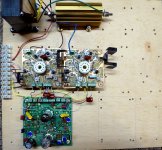
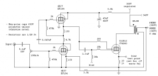
I built a P-P amp with a universal driver board, and a pair of output boards that have a separate mosfet driver with DC and AC level controls for G1, G2 and the cathode. First picture.
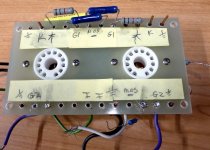
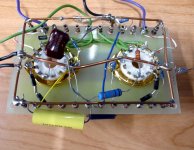
I have found several combinations that work pretty good, and yes, one of them has been reduced to a simple circuit very similar to your "crazy drive." Second and third pictures.
I have seen 75 watts flow out of a pair of tiny 6GF5's without any hint of redness. I dialed it back to 50 watts and left it run.....for a whole day. What happened? Nothing, it was still cranking out 50 watts.
Circuit, mosfet follower drives the screen through a 10 ohm resistor with a ferrite bead on each lead. The resistor is just so I can watch the screen current with differential scope probes. There is a resistor and the super secret component in series between G2 and G1, and a resistor between G1 and a negative voltage source.
The super secret component.....a zener diode. The trick is to play with the resistor and diode values such that G1 just begins to go positive at max output. The zener allows independent setting of the G1 and G2 idle voltages, while the series resistor allows for some optimization of distortion by balancing the AC drive between G1 and G2. Each tube type seems to need different parts. You can hang a small pot between the two G1 to - resistors and the negative voltage source to tweak the AC and DC balance (together) while the DC only gets set by the G2 idle voltage. These 3 pots allow for tubes that have different idle currents, and different dynamic Gm's.
Run some Schade feedback from the output plates to the driver plates to lower the output impedance, and some cross coupled feedback to the driver screens to kill any lingering crossover distortion and you have new ways to melt 13GB5's. See the LT spice file....yeah I built it, and yes it ROCKS! No the tubes didn't melt, but the yellow Sylvania paint isn't yellow any more. Its like spicy brown mustard color.
Attachments
Well, it looks like g2/g1 drive has arrived then.
I wasn't taking the idea too seriously before due to the extra complexity and voltage requirements. Then when I saw that g2 drive, combined with negative g1, caused kinks in the plate curves, and further, that g2 drive combined with positive g1 caused the plate knees to go up to higher voltage: well I wrote it off.
AJT's link to the simple 4D32 SE amplifier got me thinking that maybe g1 could be mainly used for linearity correction with small positive g1, rather than trying to get max g2 excursion reduction, the emphasis before. Happily it still takes 30% or so off the max g2 voltage, while linearizing beyond any expectation. Significant increase of the plate knees doesn't seem to occur until reaching about 40% g1 drive. This thing just squeaks through the barriers found before. And it appears to reduce the total grid dissipation as well. For just two resistors and a reduced g2 drive that looks like 6L6 g1 drive. Can't ignore that.
Clearly this is already a winner for a SE pentode amp. using Schade or local Fdbk.
I'm still concerned about how well the gm curves here fit up in P-P class aB. The curve tracer is not revealing enough to decide that. I need to build a gain tracer now. Much like a transconductance tester, it would add a small 1KHz signal to a full input signal ramp or sawtooth function. Then the the output magnitude of the 1 KHz gets displayed on an XY scope versus the ramp function. Flat gain would give a flat horizontal line. Any deviation in gain would show up as curvature or bumps in the line. Then a P-P version of the g2/g1 output stage gets tested with the sweep(s) going through the crossover point. Tweak all the Rg2g1 and Rg1k pots and tube biasing while watching the XY scope display to get it as flat as possible. More work. But this is a test instrument that has been sorely needed all along anyway.
Last edited:
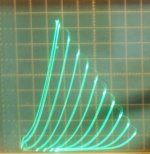
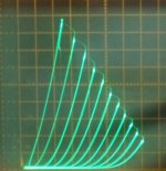
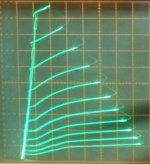
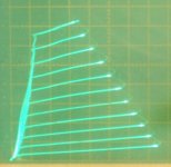
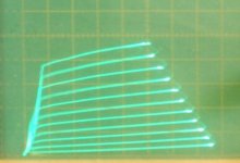
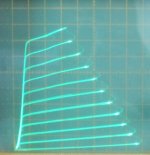
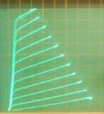
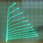
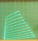
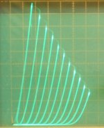
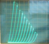
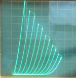
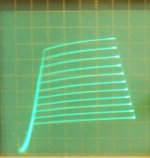
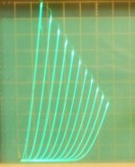
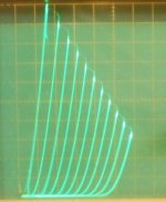
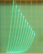
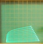
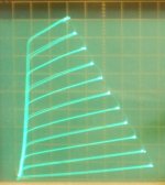
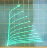
For those 6CB5 SET aficionados out there, here are some linearized g2/g1 special drive curves and g2 only drive curves for 6CB5A.
All at 50 mA/div Vert., and 50V/div Horiz.
1) 6CB5 g2 drive 80V Max g2, 7V steps on g2
2) 6CB5 g2 and g1 special drive, Rg2g1 = 3.3K Ohm, Rg1k = 1.8K Ohm (no offset LV),80V max g2, 7V Steps
3) 6CB5 conventional -g1 drive pentode
4) 6CB5 triode
5) 6CB5 Schade
All at 50 mA/div Vert., and 50V/div Horiz.
1) 6CB5 g2 drive 80V Max g2, 7V steps on g2
2) 6CB5 g2 and g1 special drive, Rg2g1 = 3.3K Ohm, Rg1k = 1.8K Ohm (no offset LV),80V max g2, 7V Steps
3) 6CB5 conventional -g1 drive pentode
4) 6CB5 triode
5) 6CB5 Schade
Attachments
Last edited:
The 6HD6/6HU5 figures pulled from the triode curves seem quite low compared with the GE datasheet, is that just due to the sample that you used or, do they all pretty much measure about the same?
For intrigue decided to take a look at what TdP did for his SE 509 design http://www.jogis-roehrenbude.de/Leserbriefe/Synola-509/Paravicini.pdf which uses g2 drive with the lovely name 'Enhanced Triode mode'. He straps g1 to the cathode so it never goes negative but tracks the signal. Shame he doesn't sell the iron for that any more.
Don't think this gives us anything tho 🙁
Don't think this gives us anything tho 🙁
When G1 starts to go positive it draws current and upsets the voltage divider changing the amount of "correction" for lack of a better term. This can be used to an advantage by playing with the divider, hence the zener diode. It allows tweaking the AC and the DC separately. Haven't tried running a large batch of tubes through it yet since I still don't have a fully working lab yet.
I have a simulation that shows there may be some merit to trying this with a common audio tube. My sim used a 6550. I haven't tried to build it yet.
LT Spice only goes so far when you apply tubes in a manner that they really weren't intended for. It is really up to the accuracy of the model, and most don't get grid or screen current right.
"The 6HD6/6HU5 figures pulled from the triode curves seem quite low compared with the GE datasheet"
?? Is this referring to the 6CB5 triode curves? That was an old pic I had on file for the triode case, so the scale and steps are likely different from the recent g2g1 curves. I can take another triode plot to get the parameters if needed. That was a Sylvania tube.
?? Is this referring to the 6CB5 triode curves? That was an old pic I had on file for the triode case, so the scale and steps are likely different from the recent g2g1 curves. I can take another triode plot to get the parameters if needed. That was a Sylvania tube.
?? Is this referring to the 6CB5 triode curves? That was an old pic I had on file for the triode case, so the scale and steps are likely different from the recent g2g1 curves. I can take another triode plot to get the parameters if needed. That was a Sylvania tube.
No, the 6HU5 curves near the top of the page. I know, there are so many curves, one begins to lose track...😛
Hmmm, you mean the 26HU5/6KD6 triode pics? Those were some I had on file too, could be off on the scaling or something. I can run the 26HU5 or 26LX6 again easily.
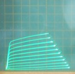
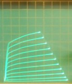
Here is g2/g1 special drive for the 38HE7 pentode. One really cheap tube that has good triode curves.
The pentode is rated 10 Watts dissipation, but one can run the pentode only by putting 21V across pins 10 and 12 (removing around 10 W of damper diode heat). That should allow 15 Watts Diss. for the pentode then.
All are 50 mA/div. Vert. and 50V/div. Horiz.
1) 38HE7 g2 and g1 special drive, 74V max g2, 7V steps on g2, Rg2g1=1.555K, Rg1k=540 Ohm
2) 38HE7 g2 drive only, 74V max g2, 7V steps on g2
3) 38HE7 triode mode 7V steps on g1
Attachments
Last edited:
Yup, that one. Do you remember what make was it? Perhaps I am comparing it to the wrong datasheet (GE)...Hmmm, you mean the 26HU5/6KD6 pics? Those were some I had on file too, could be off on the scaling or something. I can run the 26HU5 or 26LX6 again easily.
The two 26HU5 tubes here are both RCA, and the two 26LX6 are both RCA too.
I've got several 36MC6 labeled GE, RCA and Sylvania that are quite similar to the 26HU5/26LX6/6KD6 spec wise. (probably all made by RCA too since they registered it)
I've got several 36MC6 labeled GE, RCA and Sylvania that are quite similar to the 26HU5/26LX6/6KD6 spec wise. (probably all made by RCA too since they registered it)
G2/G1 drive maybe not so new, curves already in LS50 data-sheet from 1941 (very last page, figure 14): http://frank.pocnet.net/sheets/043/l/LS50.pdf
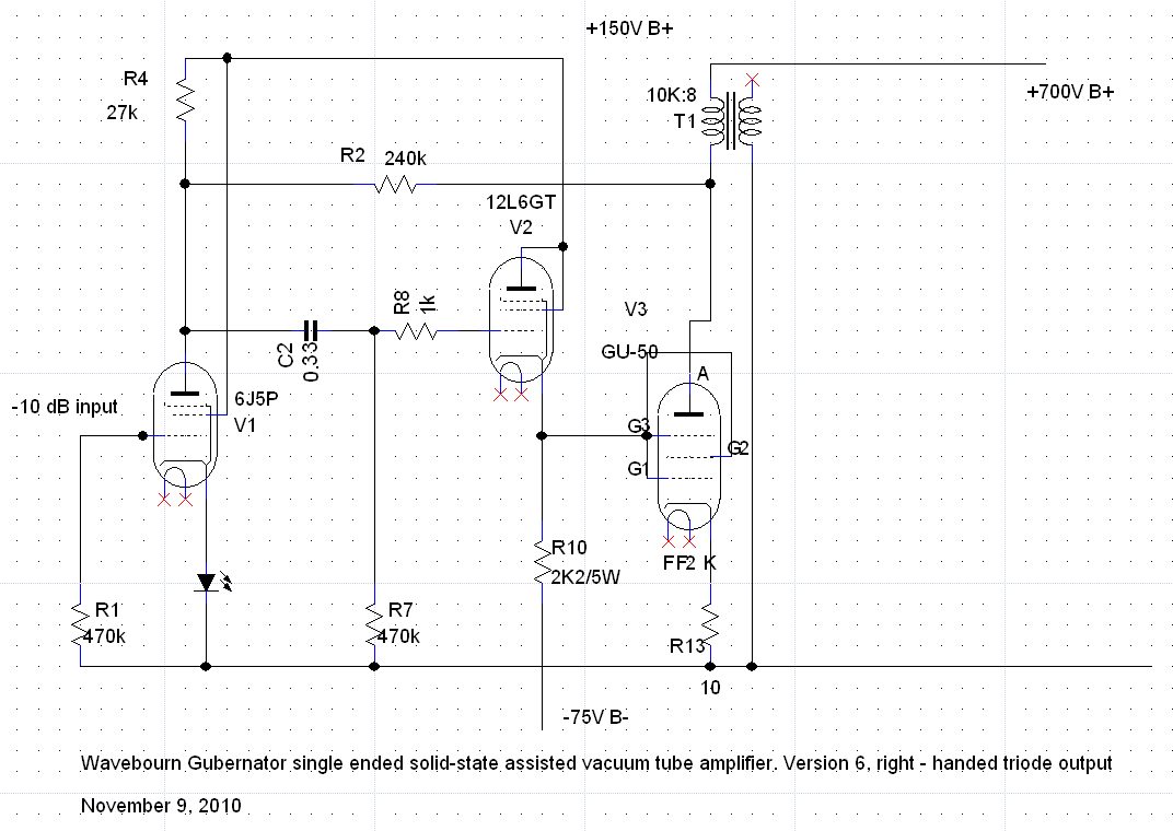
also used in Wavebourn's GU50 "Gubernator" design (he calls it "Left Handed Triode Mode"): http://www.diyaudio.com/forums/tube...-triode-configuration-what-bias-points-7.html
http://www.diyaudio.com/forums/atta...nfiguration-what-bias-points-gubernator-6.jpg
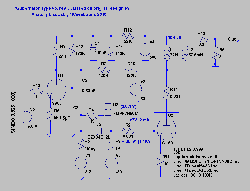
later versions have mosfet drive: http://www.diyaudio.com/forums/atta...es-gu-50-se-amp-700v-b-gubernator_mk_6b_3.png
no resistor between G2 and G1 though, does this make a big difference ... ?
also used in Wavebourn's GU50 "Gubernator" design (he calls it "Left Handed Triode Mode"): http://www.diyaudio.com/forums/tube...-triode-configuration-what-bias-points-7.html
http://www.diyaudio.com/forums/atta...nfiguration-what-bias-points-gubernator-6.jpg
later versions have mosfet drive: http://www.diyaudio.com/forums/atta...es-gu-50-se-amp-700v-b-gubernator_mk_6b_3.png
no resistor between G2 and G1 though, does this make a big difference ... ?
G2/G1 drive maybe not so new
I first saw it in a schematic of a PA amp from the 40's or 50's that ran a pair of 807's in push pull. Drive fed directly to G2, with a resistor from G2 to G1.
There was mention of "high Mu triode mode" in a data sheet for a transmitting pentode from the WWII era. I believe it had the two grids tied directly together. Can't find in now.
I tried that with a sweep tube and had to pick up parts of exploded mosfet from all over the room......twice!
Most of the g2 connected to g1 arrangements around are just an attempt to get more gm than grid1 offers alone. But g2 usually only has 10 to 25% of the gm of grid1. So not much help. And no particular linearization effect there either.
Then there are versions which are intended mainly as g2 drive, but with some partial g1 assistance to reduce the maximum voltage required for the g2 drive. (to improve safety margin for the tube and ease driver design) A resistor might be used in this case to protect g1 from overcurrents from the large g2 voltage swings used. With the resistor in the right range, it could provide "Crazy Drive" results (see below).
g2 drive is typically operating 1.5 to 1.4 (1.4 for aligned grids) power law (I = kVg^1.5)
While g1 drive is typically in a range (depending on current) around 2.0 power law (grid wire proximity to cathode effects). Combining voltage drives for both grids just gets you something in between 1.5 and 2.0, still non linear, but more gm at least.
The "Crazy Drive" found recently uses a resistor between between g2 and g1. This is essential. Large g2 drive like voltage swing is applied to the g2, and the resistor essentially current drives g1. Since g1 absorbs a higher proportion of cathode current at higher g1 voltages, it ends up with a reducing % voltage swing at higher cathode currents (due to IR drop in the resistor).
One can also look at this g1 action like a bipolar transistor. The g1 intercepts a fraction of the cathode current, and the fraction increases at higher Vg1. Call that fraction 1/Beta. So working that backward, the current gain of g1 is Beta, and the Beta falls off at higher currents (just like a bipolar transistor). This gives one a response at g1 that is compressive with higher output current. (see attached g1 current drive pic) And that can be used to counter the expansive 1.5 power law at g2.
So by selecting the resistor between g2 and g1 (Rg2g1), one can find a condition where the non-linearities of g2 ( voltage driven) and g1 (current driven!) cancel out. Leaving an overall near linear response. The amazing thing about the cancellation is that this works well over a large current range, as seen in the "Crazy Drive" plate curves. An additional resistor from g1 to cathode (Rg1k) helps to tune the tracking between g2 and g1 effects at low currents (where g1 is becoming hi-Z).
Some tubes seem to also have thermal contact potential issues from dissimilar metals bonded in the lead wires, and this may occasionally call for a small voltage drop in series with the Rg1k resistor. (a couple of SS diodes up to a couple of LEDs in series with Rg1k) Not always required. Could be dependent on individual tube manufacturing.
In any case, the results are what counts, and "Crazy Drive" or whatever it is called, has been delivering the goods well. A little Schade or local Fdbk around these things, to lower the output Z, and that proverbial 300B is going to be looking ill.
Also see this post:
http://www.diyaudio.com/forums/tubes-valves/284614-screen-driven-6kd6-se-3.html#post4572074
----------------
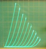
1) current driven g1 effects on plate current
2) combined g1 and g2 drives with good linearity compensation
3) g1 voltage drive (conventional -Vg1 pentode operation)
4) g2 voltage drive alone (woops different tube, close enough)
Then there are versions which are intended mainly as g2 drive, but with some partial g1 assistance to reduce the maximum voltage required for the g2 drive. (to improve safety margin for the tube and ease driver design) A resistor might be used in this case to protect g1 from overcurrents from the large g2 voltage swings used. With the resistor in the right range, it could provide "Crazy Drive" results (see below).
g2 drive is typically operating 1.5 to 1.4 (1.4 for aligned grids) power law (I = kVg^1.5)
While g1 drive is typically in a range (depending on current) around 2.0 power law (grid wire proximity to cathode effects). Combining voltage drives for both grids just gets you something in between 1.5 and 2.0, still non linear, but more gm at least.
The "Crazy Drive" found recently uses a resistor between between g2 and g1. This is essential. Large g2 drive like voltage swing is applied to the g2, and the resistor essentially current drives g1. Since g1 absorbs a higher proportion of cathode current at higher g1 voltages, it ends up with a reducing % voltage swing at higher cathode currents (due to IR drop in the resistor).
One can also look at this g1 action like a bipolar transistor. The g1 intercepts a fraction of the cathode current, and the fraction increases at higher Vg1. Call that fraction 1/Beta. So working that backward, the current gain of g1 is Beta, and the Beta falls off at higher currents (just like a bipolar transistor). This gives one a response at g1 that is compressive with higher output current. (see attached g1 current drive pic) And that can be used to counter the expansive 1.5 power law at g2.
So by selecting the resistor between g2 and g1 (Rg2g1), one can find a condition where the non-linearities of g2 ( voltage driven) and g1 (current driven!) cancel out. Leaving an overall near linear response. The amazing thing about the cancellation is that this works well over a large current range, as seen in the "Crazy Drive" plate curves. An additional resistor from g1 to cathode (Rg1k) helps to tune the tracking between g2 and g1 effects at low currents (where g1 is becoming hi-Z).
Some tubes seem to also have thermal contact potential issues from dissimilar metals bonded in the lead wires, and this may occasionally call for a small voltage drop in series with the Rg1k resistor. (a couple of SS diodes up to a couple of LEDs in series with Rg1k) Not always required. Could be dependent on individual tube manufacturing.
In any case, the results are what counts, and "Crazy Drive" or whatever it is called, has been delivering the goods well. A little Schade or local Fdbk around these things, to lower the output Z, and that proverbial 300B is going to be looking ill.
Also see this post:
http://www.diyaudio.com/forums/tubes-valves/284614-screen-driven-6kd6-se-3.html#post4572074
----------------
1) current driven g1 effects on plate current
2) combined g1 and g2 drives with good linearity compensation
3) g1 voltage drive (conventional -Vg1 pentode operation)
4) g2 voltage drive alone (woops different tube, close enough)
Attachments
Last edited:
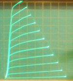
Here are the 26HU5 and 26LX6 triode curves again (RCA). I found a Zenith 26LX6 too, but looks just like the two RCA ones. All triode plots are 50 mA/div Vert., 50V/div Horiz. and 7V steps on g1.
Then pic 6) is 6L6WXT+ with the "Crazy Drive" 20 mA/div Vert., 50 V/div Horiz.
118V max g2 with 7V steps on g2. Rg2g1 = 2.64K and Rg1k = 291 Ohm
Pics 7) and 8) are 36MC6 in triode (very similar to 26LX6/26HU5/6KD6)
1) 26HU5
2) 26HU5
3) 26LX6
4) 26LX6
5) 26LX6 (Zenith)
6) 6L6WXT+ Crazy Drive
7) 36MC6 (typical)
8) 36MC6 (best one found)
Attachments
-
 rsz_26hu5_t3_7vs.jpg61.9 KB · Views: 385
 -
 rsz_36mc6s_t.jpg51.8 KB · Views: 116
 -
 rsz_36mc6m_t.jpg41.8 KB · Views: 110
 -
 rsz_6l6wxt_g2_g1_7vs_118v.jpg61.7 KB · Views: 110
 -
 rsz_26lx6_tz_7vs.jpg60.1 KB · Views: 113
 -
 rsz_26lx6_t3_7vs.jpg57.5 KB · Views: 139
 -
 rsz_26lx6_t2_7vs.jpg61.4 KB · Views: 104
 -
 rsz_26hu5_t4_7vs.jpg61.4 KB · Views: 107
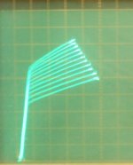
Tried some high gm tubes this time to see if they work with "Crazy Drive".
10 mA/div Vert., 50V/div Horiz., 7V steps on g2
1) 6HB6 Crazy Drive 84V max Vg2
2) 6HB6 g2 drive 88V max Vg2
3) 12HL7 Crazy Drive 80V max Vg2 (frame grid1)
4) 12HL7 g2 drive 85V max Vg2 (frame grid1)
5) 6HB6 in conventional -Vg1 drive
6) 12HL7 in conventional -Vg1 drive 100V on Vg2 and 0.4V steps on g1
The g2 drive pics are limited by the 70V sweep available from the curve tracer. Would need like twice or more step volts to expand them up to the Crazy Drive size. The 12HL7 Crazy Drive pic could be expanded up even further by Rg2g1 adjustment, but I kept it on the screen.
Attachments

Last edited:
There was mention of "high Mu triode mode" in a data sheet for a transmitting pentode from the WWII era. I believe it had the two grids tied directly together. Can't find in now.
Have a look at the LS50 data sheet, German WWII transmitting pentode, very last page: tubedata.tigahost.com/tubedata/sheets/043/l/LS50.pdf
the Germans used the parameter "Durchgriff" given in %, which is dUg/dUa or in other words 1/mu
and "Steilheit" means transconductance gm in mA/V
triode connected Durchgriff for the LS50 is given as 20% hence mu=5
triode connected Steilheit is gm=2 mA/V
G2/G1 connected Durchgriff for the LS50 drops to 0.35% which boosts mu up to 285 (!)
also gm is up at 5 mA/V.
Often the same HF transmitting tube was also used for the AF modulator amp, so the high mu G2/G1 mode came in handy for that purpose.
Speaking of the LS50/GU50, does anyone have some production design examples using the "super triode" or the "right-hand triode" connection?
Attachments
- Home
- Amplifiers
- Tubes / Valves
- Those Magnificent Television Tubes