I don't think so.
Ripple rejection? is that what in your opinion makes the sound "natural"?

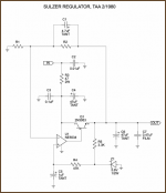
Hi Jack, I bought a lot of pin compatible single-opamps and tested each of them in my not-exactly-Jung regulator design. For some stupid reason I stopped at the AD817, instead of continuing all the way (for only USD 20 more) to the AD797. Here's the link.
You'll see that, unlike the Jung design, I powered the opamp from the input instead of the output. I also made the "Sulzer" design decision to bias the VREF generator from a regulated version of the input not the output. And finally I used a high transconductance MOSFET as the series pass element, instead of a 35 year old BJT. But hey that's just me.
You'll see that, unlike the Jung design, I powered the opamp from the input instead of the output. I also made the "Sulzer" design decision to bias the VREF generator from a regulated version of the input not the output. And finally I used a high transconductance MOSFET as the series pass element, instead of a 35 year old BJT. But hey that's just me.
Mark: As soon as i have everything uncrated I will build one of yours. Right now we're all boxes here.
Oops, you are so right and I am wrong. Here's a correction:Sulzer VREF diode is powered from the output side of regulator.
I also made the less-than-bold decision to bias the VREF generator from a regulated version of the input not the output.
Last edited:
Ripple rejection? is that what in your opinion makes the sound "natural"?
i think he was pointing out that the superreg sounded more "natural", because of the distortion spectrum.
...to which i would answer that
1) there are many variations of the salas shunt reg
2)if you define "natural" as the spectrum, in that case, for that graphics comparison, you win.
3)I of course didnt ear the two side by side, but from general experience, it is possible that one will say it sounds "more natural".Maybe it has to do with noise spectrum(which i "ear" superior with salas reg)...?
1) there are many variations of the salas shunt reg
which renders it useless for comparison -- no scientific method.
which renders it useless for comparison -- no scientific method.
Same could be said about the Jung.
So what was your point again when posting those charts of Salas vs Jung?
Last edited:
which renders it useless for comparison -- no scientific method.
what i really meant in my comparison is:
"salas regulators sound different and may please you better"
😉
I may have probably damaged the JSR lately.
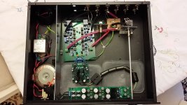
The first picture below shows the JSR powering an active crossover board with 6 opamps (OPA627, OPA2134) per channel on a 4 layer PCB.
There are small power and ground planes in the middle of the board.
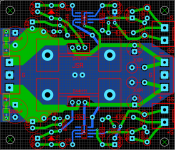
The second picture shows the JSR PCB I came up. I could not use Jidden's PCB because I wanted the +rail on the bottom and -rail on top to follow the same pattern of my other PCBs.
I lately found the sound of my system downgraded obviously. I then used my scope for trouble shooting and found the problem of the JSR negative rail mildly ringing. I see ripples of up to 2mV ptp at 660kHz.
When I disconnected the active crossover board and used the onboard dummy load of 300R on 16.5V rail with 55mA current, the ripples were gone.
I then reconnected the load and soldered the 100R and 100pF at the sensing point. This did not change the ringing behaviour.
The first picture below shows the JSR powering an active crossover board with 6 opamps (OPA627, OPA2134) per channel on a 4 layer PCB.
There are small power and ground planes in the middle of the board.
The second picture shows the JSR PCB I came up. I could not use Jidden's PCB because I wanted the +rail on the bottom and -rail on top to follow the same pattern of my other PCBs.
I lately found the sound of my system downgraded obviously. I then used my scope for trouble shooting and found the problem of the JSR negative rail mildly ringing. I see ripples of up to 2mV ptp at 660kHz.
When I disconnected the active crossover board and used the onboard dummy load of 300R on 16.5V rail with 55mA current, the ripples were gone.
I then reconnected the load and soldered the 100R and 100pF at the sensing point. This did not change the ringing behaviour.
Attachments
Last edited:
At the load, there are 2 electrolytic capacitors of 22uF with Z=0.22R at 100kHz . There are also 1R+0.1uF NPO SMD and 0.22R+0.1uF NPO SMD for damping purpose at the load.
At the JSR side, the output has 47uF with Z at 100kHz at around 0.2R.
My thought was this: since the JSR should only have at its output 100uF - 120uF, I would put 47uF there so that I can put 2 x 22uF at the load to create some low inductance path at the load. The combined capacitance is 91uF. I later added a 18uF z=1R capacitor at the load.
I then swapped the JSR with another one I built but have not used. It was also tested OK with dummy load. When plugging in this JSR it got worse. I saw ringing at the same frequency 660kHz but with ripples of 14mV ptp.
What have caused the problem? I have no idea. I have not found errors in the PCB component connection. All parts were purchased from Digikey and all transistors from OnSemi. Opamps are AD825.
How to find out the cause of the problem? What can I do to fix it?
@HiFiNutNut
I suspect there are some minor issues with the layout, but more importantly, what error amplifier are you using?
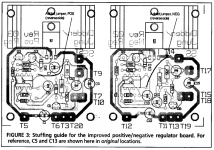
Your layout is not exactly "tight", for reference, here are images of the original boards from Old Colony (which was an Audio Amateur board house):
You also seem to have omitted the protection diodes for the error amplifier.
Use 100 or 120uF on the output ... see the article on Walt's website/blogsite for details.
I suspect there are some minor issues with the layout, but more importantly, what error amplifier are you using?
Your layout is not exactly "tight", for reference, here are images of the original boards from Old Colony (which was an Audio Amateur board house):
An externally hosted image should be here but it was not working when we last tested it.
An externally hosted image should be here but it was not working when we last tested it.
You also seem to have omitted the protection diodes for the error amplifier.
Use 100 or 120uF on the output ... see the article on Walt's website/blogsite for details.
Last edited:
Thanks, Jack.
The error amplifier is AD825. According to Jung, protection diodes are not required for AD825.
I am wondering if I need 120uF right on the output, or have 120uF in total as the load with 47uF on the output and the rest on the load board.
I am not sure about the ESR required for the 120uF output cap. Would the wrong ESR cause the ringing?
I will check Jidden's old board to see how I can tighten up my PCB tracks. I thought mine were pretty tight.
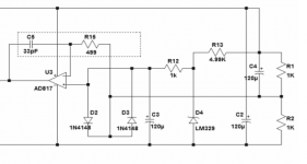
Refer to the portion of the schematic below. This is what Mr. Jung published not that long ago in his "A Universal Shunt Regulator for Audio Applications".
This portion of the schematic is almost identical to the JSR's. The added 33pF provides compensation and should provide stability.
I guess if I implement this in the JSR then I may be able to get rid of the ringing.
What do you think?
This portion of the schematic is almost identical to the JSR's. The added 33pF provides compensation and should provide stability.
I guess if I implement this in the JSR then I may be able to get rid of the ringing.
What do you think?
Attachments
I still don't understand what was happening with the ringing.
Given that the resonant frequency is around 660kHz, it is unlikely to be due to parasitic of the electrolytic capacitors or even track inductance, as their resonance frequencies should be much higher. 660kHz seems to be too low. The JSR works with resistive load, but only rings with the actual load. As you can see from the first picture I posted, there should not be large inductance to cause ringing at 660kHz.
Given that the resonant frequency is around 660kHz, it is unlikely to be due to parasitic of the electrolytic capacitors or even track inductance, as their resonance frequencies should be much higher. 660kHz seems to be too low. The JSR works with resistive load, but only rings with the actual load. As you can see from the first picture I posted, there should not be large inductance to cause ringing at 660kHz.
When I did my PCB I did make reference to Jidden's design. I was trying to make tracks shorter, not longer, to the best I could, to reduce inductance.
Of course, there may always be areas I overlooked. Please point out my errors if you find any.
Of course, there may always be areas I overlooked. Please point out my errors if you find any.
Attachments

No high Q caps are allowed!
Your problem is most likely the use of high Q caps on the rails of the op amps, if that is what you have. I think it has been stated before that this is simply not allowable. Ceramic chip caps and/or film types with milli-ohm ESR cause intolerable phase shifts, and ultimately oscillations. If you actually have them, just get rid of them. A few electrolytics are OK and the total value should not be critical.
A properly working super-regulator circuit will show NO ripple from the mains, since LF rejection is more than 100dB. A 1mV/div AC coupled scope will show a flat line at Vout, if all is well. Components at 660kHz indicate oscillation.
Sorry to butt in here, but the pain and suffering should not be.
At the load, there are 2 electrolytic capacitors of 22uF with Z=0.22R at 100kHz . There are also 1R+0.1uF NPO SMD and 0.22R+0.1uF NPO SMD for damping purpose at the load.
At the JSR side, the output has 47uF with Z at 100kHz at around 0.2R.
My thought was this: since the JSR should only have at its output 100uF - 120uF, I would put 47uF there so that I can put 2 x 22uF at the load to create some low inductance path at the load. The combined capacitance is 91uF. I later added a 18uF z=1R capacitor at the load.
I then swapped the JSR with another one I built but have not used. It was also tested OK with dummy load. When plugging in this JSR it got worse. I saw ringing at the same frequency 660kHz but with ripples of 14mV ptp.
What have caused the problem? I have no idea. I have not found errors in the PCB component connection. All parts were purchased from Digikey and all transistors from OnSemi. Opamps are AD825.
How to find out the cause of the problem? What can I do to fix it?
Your problem is most likely the use of high Q caps on the rails of the op amps, if that is what you have. I think it has been stated before that this is simply not allowable. Ceramic chip caps and/or film types with milli-ohm ESR cause intolerable phase shifts, and ultimately oscillations. If you actually have them, just get rid of them. A few electrolytics are OK and the total value should not be critical.
A properly working super-regulator circuit will show NO ripple from the mains, since LF rejection is more than 100dB. A 1mV/div AC coupled scope will show a flat line at Vout, if all is well. Components at 660kHz indicate oscillation.
Sorry to butt in here, but the pain and suffering should not be.
Mr Jung,
Thank you very much for your comment.
I have 2 electrolytic caps with impedance = 0.34R at 100kHz and one 0.1uF in series with 0.22R SMD all in parallel at the rail at the load. Do they constitute a high Q cap? I thought those are better than a ceramic or film cap.
I guess it may be due to the load having power / ground planes in a 4 layer PCB. Perhaps the close proximity between the planes works as a "high Q" capacitor causing the oscillation?
By the way, the sensing circuit in your latest shunt regulator is slightly different from the original SuperReg in that it has a 33pF capacitor between the opamp output and the opamp negative input. Would this give better stability? Can I use it in your SuperReg?
Many thanks again. As always, your comments will be very highly appreciated and regarded.
Regards,
Bill
If you have employed remote sensing as described just below, this may be part or all of the problem:
I then reconnected the load and soldered the 100R and 100pF at the sensing point. This did not change the ringing behaviour.
A 100pF value is not an effective bypass for 100 ohms. Maybe 0.01uF would work better? Or no remote sensing at all, at least to troubleshoot things.
To answer your question about "high-Q caps", look at some data sheets, and note the sharp resonance around the minimum Z. That's what I'm talking about. Adding a series R of ~0.22 ohm swamps out the resonance, yes. But then, what in the world is the use of having this type of RC network, at all? It simply isn't needed.
I doubt that your 660kHz oscillations are due to overlapping ground planes. Try the suggestions above, and see what they offer.
Thanks. I will find and buy some higher ESR caps and take out remote sensing and give it a try again.
- Home
- The diyAudio Store
- Super Regulator