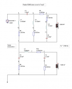
here you go, top section is the high pass and the bottom is the low pass. Where zero values are shown, it means the component is not present.I'm not familiar with the crossover nomenclature that you provided for the schematic. Could you be kind enough to provide correlation of values to position in diagram, such as below?

I can share a winpcd project file if you want to play around with it.
See:
Speaker Crossover Calculators by V-Cap
and scroll down. Alternatively, use XSim's crossover blocks, same idea.
If you were serious about this, I'd:
1. get the drivers
2. put them in your target cabinet (or baffle, whatever)
3. Measure frequency response and driver impedance separately without crossovers (OmniMic + DATS) .
3.5 Measure speakers together to calculate acoustic offsets.
4. Import to XSim
5. Design crossover.
Others recommend other tools, but this is what I like. 🙂
This won't make you a crossover designer, per se, but if you want to invest into an ideal crossover, this is what I would recommend.
If you want to compare at say, 30degrees, do the same process only create separate frequency charts AND acoustic offsets at 30 degrees. Then you can use XSim for both straight on and on-angle simulations by changing the driver files. You will only need to get the driver impedances in-cabinet once though, those are constant regardless of listener location. 🙂
Now you have a powerful tool to design 2nd and 4th order crossovers and compare them straight on and at an angle. This will tell you if it's worth doing a 4th order or not, as well as letting you play with the on-angle phase response. Maybe phase matching for the middle of your intended listening area will work better than straight on. The best part is, once you've measured your speaker drivers you can iterate through several different designs quickly. So long as you are organized about saving the results from each trial in the right place, you'll do in weeks what designers had to do in a year. 🙂
Best,
Erik
Hi Eric,
Thank you for attempting to instruct the Master! Dave R (or Dave Rosgaard) uses his own proprietary design software that he wrote himself. ( FWIW: Boeing Aircraft Co. also uses some of Dave's other proprietary software programs for different aircraft applications)
Best Regards,
TerryO
Hi Eric,
Thank you for attempting to instruct the Master! Dave R (or Dave Rosgaard) uses his own proprietary design software that he wrote himself. ( FWIW: Boeing Aircraft Co. also uses some of Dave's other proprietary software programs for different aircraft applications)
Best Regards,
TerryO
Hi Terry!
Not my intention, of course! I was answering the person who was asking about what a 4th order crossover might look like, and I how I went from amateur to an even poorer amateur faster than ever before. 🙂
Best,
Erik
no harm done. I did conjure up a crossover for these drivers as TerryO mentioned. Just curious to see what other solutions were developed. I have LspCad, and some other tools, but not V-cap, Xsim, or DATS.
Like many (most?) others here . . . my learning continues . . . 😉
Like many (most?) others here . . . my learning continues . . . 😉
here you go, top section is the high pass and the bottom is the low pass. Where zero values are shown, it means the component is not present.
View attachment 519870
I can share a winpcd project file if you want to play around with it.
Thanks so much. I have LspCad to toy with.
Hi 3ll3d00d ,
The zip file with blended data does not have minimum phase for the woofer file. Is there possibly a different file intended?
TIA,
The zip file with blended data does not have minimum phase for the woofer file. Is there possibly a different file intended?
TIA,
it looks like I included the wrong one in those zip files, here's a corrected zipHi 3ll3d00d ,
The zip file with blended data does not have minimum phase for the woofer file. Is there possibly a different file intended?
TIA,
View attachment 5208c_xo_design.zip
I now see there is a time limit on editing posts so I can't make this clear in the earlier post (but perhaps a mod can fix it)
Last edited:
would be interesting to see what you came up withno harm done. I did conjure up a crossover for these drivers as TerryO mentioned. Just curious to see what other solutions were developed.
mine is acoustically 4th order 🙂I was answering the person who was asking about what a 4th order crossover might look like

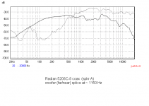
two other bits of info that might be useful, some distortion measurements (which is what led me to aim for around 1.5kHz)
cd

woofer

cd
woofer
Thanks for providing the min phase file for the woofer, 3||3d00d. Nice work btw. My design has similar spl response, but the impedance and acoustic phase differ somewhat. I imported your data files into the series crossover sim. The drivers are different enough that several changes to components are required to get a similar response, but I believe the acoustic phase could be improved. If you're interested, I'll have more time in the next week or so to work on that.
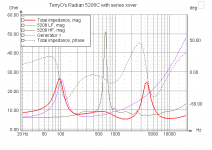
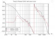
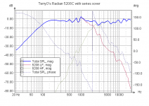
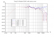
A few snapshots from TerryO's 5208C crossover design.
The raw spl of the LF and HF was similar to 3||3d00d's. But there are some noticeable differences.
The xover is series, just because I was interested in seeing what could be done with this coax. The crossover point was just above 2 kHz.
The result seemed to be a good balance of SPL, impedance, and acoustic phase. In fact, it is probably the best match of acoustic phase over the broadest range that I've dealt with (so far). 🙂
Attachments
That would be very interesting, thanks.. If you're interested, I'll have more time in the next week or so to work on that.
I wonder where that mess around 8-10kHz comes from in mine.The raw spl of the LF and HF was similar to 3||3d00d's. But there are some noticeable differences.
And now for the polars, please?
I don't believe I have that modeling capability. Unfortunately, I did not save any off-axis measurements. However, I seem to recall that the response off-axis was fairly good as well.
They went home to a single (lonely) listener who does not need to share the sweet spot. 😀 Maybe someday I can get them back and collect some off-axis data.
Last edited:
Here's a shot of the off-axis from my sim. (not the pretty colored contour plot)
There is something going on somewhere beyond 15 and 30 deg off axis. From prior experience, actual measurements off-axis don't necessarily show those nulls. Is this an inherent characteristic of the driver? Or is it influenced by the crossover?
Someday, I would like to take off-axis measurements to compare to the sim.
Attachments
wow a lot of replies to digest. It looks like the Fs is a little higher than the published specs. does anyone have any copies of galante rhapsody xover design?
Silly question: Those resistors in series with the inductors are the actually dc resistance of the inductors and not additional series resistance correct?
just to be clear, the specs I published are the (current) official specs (as far as I know anyway, they come straight from Radian Audio so you'd hope they are official!)It looks like the Fs is a little higher than the published specs
if you mean on my schematic, yes (DCR)Those resistors in series with the inductors are the actually dc resistance of the inductors and not additional series resistance correct?
Last edited:
As far as T/S parameters... just wondering why its so different from:
Radian Audio 5208C Coaxial Speakers - Radian Dual Concentric 5208C 8" time aligned coaxial speakers. Radian 5208C coaxial speaker - Radian 5208C coaxial speaker handles 200 watts RMS. Radian 5208C 8" coaxial driver is available here. Radian coaxial s
Thanks!
Radian Audio 5208C Coaxial Speakers - Radian Dual Concentric 5208C 8" time aligned coaxial speakers. Radian 5208C coaxial speaker - Radian 5208C coaxial speaker handles 200 watts RMS. Radian 5208C 8" coaxial driver is available here. Radian coaxial s
Thanks!
- Home
- Loudspeakers
- Multi-Way
- Radian 5208c coaxial project