Affirmative
Hello Derek,
For the most part I agree with your list of rules to follow,
and, I'd really like to emphasize this one:
(4) I only ever use sealed box for any and all driver loading....I have even abandoned open baffle!
Obviously, you have arrived at this list through vast experience added to sound design and engineering practices.
I believe I will have a cup of tea. Good day 🙂
But subject to the above I might be able to help save you some time and effort with some general advice.....:
(1) Use the max desired SPL in the mid and top to as the reference for your bass / low midrange performance. For example a SAM might require 96dB continuous with 102dB peaks at 1 meter as a rough guide.
(2) Select a bass / mid capable of matching the SPL at your desired bass cut off without exceeding Xmax or its thermal limit.
(3) IMO if any bass / mid has to move more than plus / minus 6mm you need to use a bigger driver or more of the same driver.....Minimise cone movement at all costs....Less is ALWAYS more!!
(4) I only ever use sealed box for any and all driver loading....I have even abandoned open baffle!
(5) I believe a Q of 0.707 is the all round best compromise in most cases.
(6) NEVER use any driver with a rubber surround.....Only linen, cotton, silk or a combination of these materials.
(7)The only TS parameters I look for are a good "fast" driver ie Low Mms and high Bl. High power handling is very important but huge XMax is a waste of time.....Whether or not a driver can do plus minus 10mm or 12mm Xmax, I never ask a driver to do this....Better to observe point 3 above.
(8) As a rule of thumb, in order to get the -3dB point bass response down to 45Hz (SAM) 6.5 and 8 inch drivers need a min 2 inch voice coil, 10 inch driver needs 3 inch VC to reach 38Hz (SAM), a 12 inch driver needs 4 inch VC to reach 30Hz (MAM) and 15 inch driver a 4 inch or 5 inch VC to reach around 20Hz (LAM) handle the power after Eq'ing the low end in a small sealed box design.
I hope the above helps and all the best
Derek.
Hello Derek,
For the most part I agree with your list of rules to follow,
and, I'd really like to emphasize this one:
(4) I only ever use sealed box for any and all driver loading....I have even abandoned open baffle!
Obviously, you have arrived at this list through vast experience added to sound design and engineering practices.
I believe I will have a cup of tea. Good day 🙂
if you set the box to Butterworth and F-3dB=120Hz then you also need to set the electrical filter to Butterworth and F-3dB = 120Hz.
That gives you a acoustic 4pole rolloff matching an LR4 @ 120Hz.
Your low bass speaker has to come up to that value to match through the crossover from low bass to upper bass.
If you keep the Butterworth box size @ 120Hz and add on the LT to convert it to Butterworth F-3dB=80Hz, you can now add on the Butterworth electrical filter @ F-3dB = 80Hz.
You now have an equivalent to a 80Hz LR4 acoustic filter.
Your 80Hz low bass can now be filtered to match the LR4 characteristic and you have the correct LR4 80Hz crossover.
But you have to allow for the LT in you upper bass speaker.
It will add on a BIG power requirement to the bottom part of the upper bass response.
It might double the power or maybe as much as triple the power required.
That brings a 300W amp driving a 300W down to an effective 100W amp driving a 100W speaker to whatever SPL that would give for the upper bass speaker.
If it's only 2times it would be the equivalent to 150W amp driving a 150W speaker.
In summary:
Match the LR4 for the crossover between the two speakers.
Adjust the LT affected power rating to reflect the SPL obtainable at the ear.
Hello Derek,
For the most part I agree with your list of rules to follow,
and, I'd really like to emphasize this one:
(4) I only ever use sealed box for any and all driver loading....I have even abandoned open baffle!
Obviously, you have arrived at this list through vast experience added to sound design and engineering practices.
I believe I will have a cup of tea. Good day 🙂
Cheers Scott....May I join you with an organic Earl Grey with a teaspoon of Manuka honey and a splash of Royal Dutchy organic milk!!
Nice N' Easy does it....
To the OP,
Looking at all the complex crossover theory and implementation, I am confused....God knows how you must be feeling!
Forget about all that crossover theory derived from mid last century textbooks / loudspeaker design cook book stuff, here is my cookbook advice!
Ingredients-
Four (two per side) high performance Pro drivers that will easily produce very high SPL with low distortion over a 60Hz to 800Hz band.
One 500 watt into 8 Ohms 750 or more into 4 Ohms power amp.
One DSP crossover or AV amp used as DSP crossover & Eq.
Selection of good quality interconnects and power cords.
Cooking instructions:
Connect the Beyma drivers in parallel (approx 4 Ohm load) to the power amp.
Set the DSP crossover for 48dB per octave slope at 80Hz. Linear phase if you have a high end DSP, Butterworth or Linkwitz if not.
Set the same 48dB slope for your mid / tweeter crossover.
Plug in a low cost measurement mic and take a series of room measurements at your listening position and within a meter or so left / right and front / rear to get a good overview of the room speaker interface.
Use the main listening position to Eq to taste....If you are new to DSP, this will take a few days or weeks depending on you fast a learner you are and what DSP you are using.
Let it all cook for a few more days while you listen and Eq to taste.
Enjoy!
Cheers
D.
I definitely appreciate the discussion!
First screenshot is the 10G40 in UniBox at 150W, minimal stuffing, and a 10.3 liter box represents Qtc=0.71. In line with Derek's calculations.
I'm thinking heavier filling to minimize reflections from the box and back out through the driver, so the second screenshot is set for "walls covered" and a 9.4 liter box represents Qtc=0.71.
I model one driver because I'm planning a sealed enclosure for each driver. But I'm also planning for two drivers per side, so then I modeled two drivers in paralel in an 18.8 liter enclosure, at Qtc=0.71. That's the third screenshot.
The amp on hand is a Hypex UcD400, rated at 400W, but I believe it has clean output up to 300W so that's my upper limit for the purpose of my calculations. The amp will only drive the 10G40s, in parallel. Hence in UniBox I use 150W to each driver.
The chart displays frequency response of the two drivers in an 18.8 liter box, driven at 150W per driver. It shows at 80Hz and 150W per driver these would reach 114dB SPL. I envision DSP triming everything above the 80Hz point so SPL would look flat and the maximum achievable SPL would be 114dB.
I usually listen at 80-85dB SPL,sometimes going to 90dB, and rarely above that. Seems 114dB would be plenty of headroom. BTW, at 114dB at 80Hz each driver is displacing 4mm vs 7mm Xmax.
At least those are my thoughts! What do you think?
Just some derating: 114 at 1m = about 102m at 4m, but you'll get room contribution bringing that back up at least 3 dB, ignoring room modes for a minute. So you're at 105 dB.
Peak to average ~ 20 dB to avoid peak clipping, you end up with 85 dB ave at the listening spot
Its up to you. Like you said each driver isn't hitting xmax, you have almost 6 dB more output or more to plumb there. Not trying to dissuade you from using these drivers, just wondering why these when maybe you can find a better fit for your application?
To do this right, I think it has to be calculated out and then a personal judgement made whether that's loud enough for you. If you already have the drivers though, might as well give them a shot.
I don't get the approach of dropping thousands on parts before making a few simple calculations to double check what the limitations are
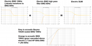
For electric domain here some visuals how many dB needed for Linkwitz transform 109Hz BW2 to 80Hz BW2, and also when cascaded a HP BW2 80Hz.
Last plot show acoustic domain.
So its only 1 dB, great post Brytt!
So its only 1 dB, great post Brytt!
Thanks and yes only about 1dB even LT boost is over 5dB approaching to DC but then HP BW2 80 seems save situation a lot.
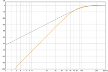
Picture 1 is zoomed scale of acoustic plot from previous post, driver slope 109Hz BW2 at -3dB and system slope 80Hz LR4 at -6dB. Boost from LT stops around -7,8dB then electric 80Hz BW2 filter takes over as seen picture 2.
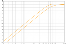
Picture 3 is to show electric signal routed to driver had it been inherent acoustic 80Hz BW2 verse the one that in same 80Hz BW2 HP filter also transform 109Hz Q.7071 to 80Hz Q.7071.
Should any be interested plots are created at 16bit/48kHz by pointing REW to output to JRiver's virtual soundcard then all the filters one can set inside JRiver DSP engine plots nice into REW.
Attachments

Last edited:
Just some derating: 114 at 1m = about 102m at 4m, but you'll get room contribution bringing that back up at least 3 dB, ignoring room modes for a minute. So you're at 105 dB.
Peak to average ~ 20 dB to avoid peak clipping, you end up with 85 dB ave at the listening spot
Its up to you. Like you said each driver isn't hitting xmax, you have almost 6 dB more output or more to plumb there. Not trying to dissuade you from using these drivers, just wondering why these when maybe you can find a better fit for your application?
To do this right, I think it has to be calculated out and then a personal judgement made whether that's loud enough for you. If you already have the drivers though, might as well give them a shot.
I don't get the approach of dropping thousands on parts before making a few simple calculations to double check what the limitations are
Fair enough. The thing is I did do the homework over months, although maybe I did it wrong. But I asked for feedback over several months to understand what I needed to buy and really thought the 10G40 was a good choice, then I went off and purchased 2 to try out even though my plan calls for 4 drivers. I looked into 25 drivers...
What is it you don't like about the 10G40? The other top contenders I was suggested had much higher F3 at Qtc=0.71, and many had higher Le and higher Mms/BL.
FWIW, total SPL would be for 2 speakers (4x10G40), so additional 3dB SPL. Still borderline from your point of view I guess, but it's 88dB instead of 85dB... 🙂
Last edited:
Thanks and yes only about 1dB even LT boost is over 5dB approaching to DC but then HP BW2 80 seems save situation a lot.
Picture 1 is zoomed scale of acoustic plot from previous post, driver slope 109Hz BW2 at -3dB and system slope 80Hz LR4 at -6dB. Boost from LT stops around -7,8dB then electric 80Hz BW2 filter takes over as seen picture 2.
Picture 3 is to show electric signal routed to driver had it been inherent acoustic 80Hz BW2 verse the one that in same 80Hz BW2 HP filter also transform 109Hz Q.7071 to 80Hz Q.7071.
Should any be interested plots are created at 16bit/48kHz by pointing REW to output to JRiver's virtual soundcard then all the filters one can set inside JRiver DSP engine plots nice into REW.
Hi Brytt, so I read this wrong, the amp is being asked for 5 dB more output over the range of the LT?
Thanks and yes only about 1dB even LT boost is over 5dB approaching to DC but then HP BW2 80 seems save situation a lot.
Picture 1 is zoomed scale of acoustic plot from previous post, driver slope 109Hz BW2 at -3dB and system slope 80Hz LR4 at -6dB. Boost from LT stops around -7,8dB then electric 80Hz BW2 filter takes over as seen picture 2.
Picture 3 is to show electric signal routed to driver had it been inherent acoustic 80Hz BW2 verse the one that in same 80Hz BW2 HP filter also transform 109Hz Q.7071 to 80Hz Q.7071.
Should any be interested plots are created at 16bit/48kHz by pointing REW to output to JRiver's virtual soundcard then all the filters one can set inside JRiver DSP engine plots nice into REW.
Brytt,
Thank you for taking the time to do this! I'm a bit embarrassed to admit I don't know enough to interpret what these mean...
Am I right to understand you are modelling how a sealed box + an electric circuit for a Linkwitz Transform + another circuit for a a 2nd order Butterworth crossover? If this was so, how would it be different if I used the sealed box + DSP to trim so to keep it flat above 80Hz?
Thanks again!
I don't think the problem can be pointed solely at your 10G40.Fair enough. The thing is I did do the homework over months, although maybe I did it wrong. But I asked for feedback over several months to understand what I needed to buy and really thought the 10G40 was a good choice, then I went off and purchased 2 to try out even though my plan calls for 4 drivers. I looked into 25 drivers...
What is it you don't like about the 10G40? The other top contenders I was suggested had much higher F3 at Qtc=0.71, and many had higher Le and higher Mms/BL.
FWIW, total SPL would be for 2 speakers (4x10G40), so additional 3dB SPL. Still borderline from your point of view I guess, but it's 88dB instead of 85dB... 🙂
It's the low crossover frequency that is the cause of the problem.
I consider the low bass speaker's limitation to a maximum of 80Hz to be the main problem.
If that were 100Hz, or 110Hz most of the problem goes away. If it allows a cross @ 120Hz there is no problem to solve. LR4 @ 120Hz perfectly suits the 10G40 since that can be obtained in a small sealed box with a BW2 electrical filter
fwiw you can simulate this yourself using acourate. For example use generate iir filter to create a BW2 high pass filter (use q = 0.707 and the corner frequency), you can then add an LT by entering the biquad coeffs directly (e.g. using the minidsp spreadsheet to calculate the values) and then convolve one curve by the other to obtain the sum. This is an easy way to experiment to see what different filter combinations look like when you put them together.Am I right to understand you are modelling how a sealed box + an electric circuit for a Linkwitz Transform + another circuit for a a 2nd order Butterworth crossover? If this was so, how would it be different if I used the sealed box + DSP to trim so to keep it flat above 80Hz?
I don't think the problem can be pointed solely at your 10G40.
It's the low crossover frequency that is the cause of the problem.
I consider the low bass speaker's limitation to a maximum of 80Hz to be the main problem.
If that were 100Hz, or 110Hz most of the problem goes away. If it allows a cross @ 120Hz there is no problem to solve. LR4 @ 120Hz perfectly suits the 10G40 since that can be obtained in a small sealed box with a BW2 electrical filter
I see. Here are measurements of a sub almost identical to mine: Rythmik 12", servo-driven, in 56 liter sealed box: DIY Rythmik Audio Direct Servo 12" sealed 56L - Home Theater Forum and Systems - HomeTheaterShack.com
Do you think I can cross it over higher than 80Hz? Maybe my conclusions from looking at this are wrong and I'm building on faulty foundations.
Short term compromise needed
Hiya,
I think you are in a good position to build an excellent system, but you will need to make a slight compromise in the short term.
You need to pick the lesser of two evils....
(1) Crossing over a remote (ie not underneath or close to the main speakers) subwoofer above 80Hz is a mistake.
THX certification is 80Hz for a reason....The majority of listeners can localise sounds above 80Hz, above 120Hz easily and at 150Hz you have a muddy distorted mess.
(Many commercial systems allow a high Fs sub crossover....They all sound ****!)
(2) Slight reduction in the max SPL available in the 80Hz to 160Hz octave.
If you check out the BMR thread I post a lot on, one of the guys (Jason) had a very similar situation re crossing over his big rubber surround subs (might have been Rythmiks?) to a fast low midrange set up (4 BMR's) and he ended up dropping the crossover point and living with lower SPL's....He was very happy with the compromise.
He is now looking to ditch his rubber surround subs and build a pair of sealed subs using Precision Devices 15 inch drivers....Cotton surround, light cone, huge voice coils....Fab!
You will hear a massive improvement in bass if you ditch the Rythmiks and build a pair of subs using some nice 12 or 15 inch Beyma drivers in sealed boxes....
The Beyma SM 115 K is the best value I have ever found for real bass....Great power, extension and slam, but also incredibly tight, fast and textured....Bowed Cello and upright bass sounds gorgeous!
Solution in the longer term:
(1) A pair of sealed 50 litre cabinets (heavy birch, not MDF) with solid brass spikes to anchor and "earth" the cabinet / vibrations.
(2) A good 500 watt stereo power amp with the SM 115K's and you will be in another world.....Vastly superior to ANY heavy coned, rubber surround 6 inch Xmax monster at any price!
I can prove this with a demo as I keep one of these subs on hand for this very reason.
All the best
Derek.
Hi Brytt, so I read this wrong, the amp is being asked for 5 dB more output over the range of the LT?
Pls ignore this post, Amp is being asked for 1 extra dB (note to self: read the slides)
I agree, if spending this sort of loot, don't cross higher than 80 Hz, unless you can make this a real 3 way and not a separate sub
117dB at 80Hz with ZERO Eq.....Not too shabby!
Using my own sim, a pair of 10G 40's per side, each driver in its own sealed Vb of 17 litres (10. 7 litres Vb, plus 2.5 litres for driver volume,plus 3.8 litres for cabinet wall damping) is good for 117dB at full 400 watts AES power...With zero Eq!
You can pretty much leave the low end "flat" and slightly pull down the 100Hz to 1,600 Hz if you need to.
The trick with Eq is to pull down the peaks untill the are more in line with the low end.
Boosting low end is more complex, still doable but harder to get right.
At this 117dB SPL the drivers will also be very close to their Xmax.
So to be safe, allow 5dB head room and you will have a "safe" 112dB available at 80Hz....You will need ear protection my friend!
Now this is a Sim, and I can tell you that it wont work out quite as loud due to your 80Hz crossover slopes not being brick-wall (unless you have DEQX?).
On the other hand room gain and having two speakers (the above is for a single loudspeaker with twin drivers) will more than compensate for the driver having to work a bit below 80Hz.
Bottom line is you have way, way, way plenty of headroom.....Twin 10 G 40's per side will rock and give your TPL tweeters a run for their money!
Also the 52g Mms with a good Bl of 17 gives good ratio of 3.05.
I used to use twin Volt 2500.4 with 54g Mms and 15.5 Bl giving a slightly "slower" driver ratio of 3.48. They were sweet sounding in sealed box, also great in open baffle, see attached....But thats all in the past now!
Cheers
Derek.
Attachments

Last edited:
Brytt,
Thank you for taking the time to do this! I'm a bit embarrassed to admit I don't know enough to interpret what these mean...
Am I right to understand you are modelling how a sealed box + an electric circuit for a Linkwitz Transform + another circuit for a a 2nd order Butterworth crossover? If this was so, how would it be different if I used the sealed box + DSP to trim so to keep it flat above 80Hz?
Thanks again!
Welcome but no need to be embarrassed, maybe get back later and see if i can explain in logic way why we pointed to exact those filters, but in short as you write can't i just trim with DSP, and in principle yes.
Below add a sim from another program to yours and Overkill Audio's sealed box sims for 10G40. At 400 watt input excursion is not at max yet and wow it can play loud and you plan 2 per side, also there is a 1/4 wave rule that say if ctc spacing is at 1/4 wave length or below drivers would radiate as one and offer 3dB more, so for example if your ctc spacing is 350mm then all frq from 245Hz and down will get a boost and radiate as one driver. Because i show LR8 80Hz target below is because if you have FIR power to repair 720º phase turn that eight order filter distort, one can get less stress on driver at very lows and in XO region outside design/listening axis one loose power response because of ctc spacing and comb filtering, therefor if one go steeper filter XO region get more narrow and thereby a less area to loose power response into room. A word regarding spl myself enjoy a 90dB 10" woofer together a 87dB 3" full ranger into 25 sq meters and don't miss volume : )
Attachments

Good points...!
An excellent post Byrtt!
In paricular well done on the CTC spacing....I am so used to the BMR's crossing over at between 80Hz and 300Hz that I forget other folks still crossover at nearer 2KHz where CTC is a big deal!
One idea to help with the CTC issue is;
(1) Cut a slightly longer and wider rectangular baffle and fit the TPL in the middle but off set to one side....Like an MTM reduced in length so the two bass chassis are only about 50mm to 100mm apart and the TPL is mounted as close to the centre as it will go, but off-set to one side allowing for separate rear chambers for all 3 drivers.
As a bonus this really helps eliminate the baffle step issue, esp if you go all creative with the baffle shape and introduce asymmetry. Proac used to offset tweeters back in the 80's and I remember liking them.
This is how I did it with the twin Volt 2500.4 and a TPL.
There might be some pics posted back about 5 years ago??
- Status
- Not open for further replies.
- Home
- Loudspeakers
- Multi-Way
- Which Q? 0.50 vs 0.71