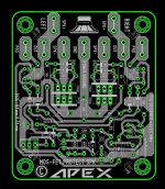
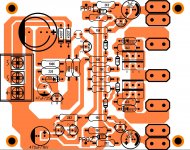
Nice work,as usual.🙂Another PCB layout for mosfet relay protect ,not tested yet 🙂
Regards,Alex
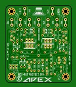
Post this in black&white😉
Thanks.
After etching I noticed a missing resistor. I added it to the sprint file and will just fit it in on the pcb I already etched. Let me know if I am right about this.
Thanks, Terry
There is two more mistakes 100k instead 3k3 and protect LED must be connect like this.
Attachments
There is two more mistakes 100k instead 3k3 and protect LED must be connect like this.
Hi Mile,
Thanks for the correction. I see Alex has the 3k3. Is the LED an added feature? I don't see it on the schematic. I thought c08bm just added it to show on condition.
Thanks, Terry
Does this look correct now?
Attachments
Last edited:
Hi Mile,
Thanks for the correction. I see Alex has the 3k3. Is the LED an added feature? I don't see it on the schematic. I thought c08bm just added it to show on condition.
Thanks, Terry
Does this look correct now?
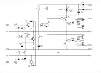
Schematic with LED
Attachments
Led was from protection with usual relay schematic, didn't think it trough.
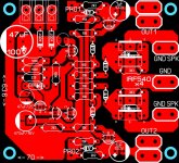
Also i run out of to220 mosfets so i modified to fit to247 ones (like IRFP 240, but also fits to220 ones) and made board smaller.
Sorry for wrong pcb mr Terry
Sprint layout file attached
Also i run out of to220 mosfets so i modified to fit to247 ones (like IRFP 240, but also fits to220 ones) and made board smaller.
Sorry for wrong pcb mr Terry
Sprint layout file attached
Attachments
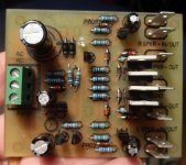
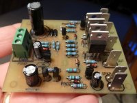
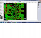
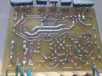
Can some one with fresher eyes take a look and see i missed something, this is my second channel and when turned on my light bulb will go bright and my psu doesn't even work(led wont even light on). Thanks for the help.
Attachments
Led was from protection with usual relay schematic, didn't think it trough.
Also i run out of to220 mosfets so i modified to fit to247 ones (like IRFP 240, but also fits to220 ones) and made board smaller.
Sorry for wrong pcb mr Terry
Sprint layout file attached
Nice pcb, thank you.
Regards
Hi Mile, IRF540 Rds(on)Ω=0.O77.
Two parallel IRF540 are Rds(on)=0.033Ω
Is it possible to parallel more IRF540 in each channel?
Two parallel IRF540 are Rds(on)=0.033Ω
Is it possible to parallel more IRF540 in each channel?
Hi Mile, IRF540 Rds(on)Ω=0.O77.
Two parallel IRF540 are Rds(on)=0.033Ω
Is it possible to parallel more IRF540 in each channel?
Use IRF1407...
hello mister Mile I have a question, is the protect from post #5546
can be use on AX-14 too 🙂
Regards
Juan
Protect can be use on AX14 and many other amps
Regards
Protect can be use on AX14 and many other amps
Regards
wow ! I'm going to also made a layout for it thanks for let me know mister Mile 🙂
Regards
Juan
Led was from protection with usual relay schematic, didn't think it trough.
Also i run out of to220 mosfets so i modified to fit to247 ones (like IRFP 240, but also fits to220 ones) and made board smaller.
Sorry for wrong pcb mr Terry
Sprint layout file attached
Hi c08bm,
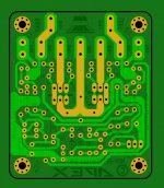
shouldnt the PGND be connected with the drain of mosfets as in schematic and alexmm layout ?
regards'
prasi
Sorry,my mistake, just now i see that 2 IRF540 connected in series for eatch channel.So the Rds(on)=2x0,077=0,154Ω.Hi Mile, IRF540 Rds(on)Ω=0.O77.
Two parallel IRF540 are Rds(on)=0.033Ω
Is it possible to parallel more IRF540 in each channel?
Hi Mile,
Can you please check the layout in post #5504? I am testing it and I have 150mV offset. I measured and pin #4 is pulled down to 0.3V. If I pull the IC then pin #4 goes to 15V but pin #7 drops to 3V and the offset goes to 15V. If my layout is right then something is wrong with the circuit.
Thanks, TerryThe -IN is sensitive to pick up.
Keep it's resistor very close to the -IN pin.
Last edited:
Hi c08bm,
shouldnt the PGND be connected with the drain of mosfets as in schematic and alexmm layout ?
regards'
prasi
Maybe I'm looking at it wrong, but the drains are connected to PGND. The difference is that the Alex connected the two grounds together on the board and c08bm didn't.
Alex is according to schematic,c08bm isn't.Maybe I'm looking at it wrong, but the drains are connected to PGND. The difference is that the Alex connected the two grounds together on the board and c08bm didn't.
- Home
- Amplifiers
- Solid State
- 100W Ultimate Fidelity Amplifier