if my mind serve well there is a wrong in the potentiometer connection
What is correct schematic or pcb?
What is correct schematic or pcb?
Last edited:
if my mind serve well there is a wrong in the potentiometer connection
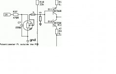
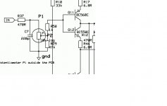
If you use page #336, yes P1 and P2 should swop position.
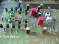
look this .
First image is pcb arrangement when second is what schematic show.
What is wrong?
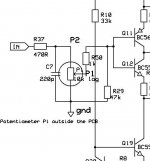
No it should be like this, just P1 and P2 interchanged positions on the schematic.
Attachments
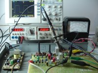
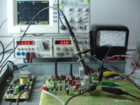
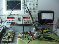
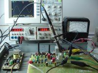
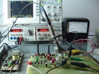
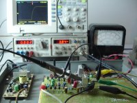
It is alive!
First test.
+/-15v
offset without servo=12mV
offset servo used=3mv
1v RMS inp 19.6vpp out ,6,68vRMS
-3db 700kHz
Rise time 590ns
First test.
+/-15v
offset without servo=12mV
offset servo used=3mv
1v RMS inp 19.6vpp out ,6,68vRMS
-3db 700kHz
Rise time 590ns
Attachments

No it should be like this, just P1 and P2 interchanged positions on the schematic.
Thanks for clarifying that dadod. It seems I have a mistake on my board.
ALTERNATIVE PARTS
Is it ok using IRF830 instead of DN2540?
I haven't any 500R multiturn,can i use 1K?
In position 1N4248 what other?
Is it ok using IRF830 instead of DN2540?
I haven't any 500R multiturn,can i use 1K?
In position 1N4248 what other?
Last edited:
No irf830 can not be used. It's depletion.. For the diode, there are lots of possible replacements, but the one used is very much a standard part and very easy to source.
Don't see any issues with a other pot. Just change ten input impedance to match. However in my expirence higher impedance also results in higher noise.
Don't see any issues with a other pot. Just change ten input impedance to match. However in my expirence higher impedance also results in higher noise.
Is it ok using IRF830 instead of DN2540?
I haven't any 500R multiturn,can i use 1K?
In position 1N4248 what other?
AS MiiB said DN2540 is depletion mode mosfet and IRF830 is enhanced mode.
You can use 1k trimpot and 1N4248 is a type failure, should say 1N4148.
Thanks for your answers, so it will be 3 weeks waiting🙁AS MiiB said DN2540 is depletion mode mosfet and IRF830 is enhanced mode.
You can use 1k trimpot and 1N4248 is a type failure, should say 1N4148.
Vgs/Rsource. Only issue is that the part is not so consistent, and thus the R needed for a certain current varies a bit. I normally have two parallel resistors, as to be able to adjust the value to suit.
Last edited:
So it about 250-350mA ?
No, it is set to about twice the GainWire supply current, means between 90 mA and 120 mA.
No, it is set to about twice the GainWire supply current, means between 90 mA and 120 mA.
So each DN2540/each rail voltage set betwen 90 - 120 mA ?
So each DN2540/each rail voltage set betwen 90 - 120 mA ?
Yes. As I showed different output stage current(higher current for low impedance headphones) you choose the CCS current according to this.
- Status
- Not open for further replies.
- Home
- Amplifiers
- Solid State
- No NFB line amp (GainWire mk2)