Crosstalk....
Because parts aren't turned on the parasitic capacitance is like having several mini antennas? Meh, might not be anything amoutnable. Perhaps there's a coupling scheme for RD bypass, and/or an orientation for cancellation.
Good work!
Does anyone see a problem with using the relays like this, to save space on the board?
Looks good to me in general.
Some minor details perhaps could be put into consideration when carrying out the real layout design:
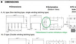
1) miniature relays such as Fujitsu Takamisawa A-series have "helper" permanent magnet in them, and require power to be applied to coil in correct polarity, pin 1 of the relay must be at positive potential (picture attached). Otherwise the relay wont fire despite sufficient current in the coil. Your layout is correct if it is top view shown.
2) If layout is to be made Fujitsu miniature relay compatible, the common positive supply to the coils may have to run on the bottom side of the PCB, As the small relay does not have a skipped pin space between the coil pins and the signal pins.
3) I don't know how much a guarding ground trace around the signal traces and pins can help keeping crosstalk down. Using small relays makes it very hard to deploy guarding ground traces if possible at all, as it would require three traces to go between the pins 2.54mm apart, quite do-able if SMD mount the relays though. However if SMD mount the replays, they must be spaced apart much more to allow a soldering tip to go in between. Seems to be a dilemma here.
4) Is a 4-conductor input signal connector for each relay more suitable, so that L and R signals can have their individual return/shield back to the RCA jacks? I usually use RG174 to wire off the RCAs, so a 4-pin connector will help in my case.
Just some thought. I may have gone too far over.
Attachments
Good points.
1: I defaulted to Panasonic AGN. Those Fujitsu relays have still yet another layout than the Panasonic AGN. Maybe it is possible to support them with some trickyness.
2: Maybe not, it depends on whether there is any danger running 12mA through a 10mil or so trace. I doubt it.
3: Notice the ground plane. The improvement over that from a top layer guard trace would probably be insignificant. And the capacitance is probably what, 5pF? Consider that the source cable probably already has 200pF at least shunting the signal, so this is really a very small problem if at all.
4: Ground switching opens a path large for RF ground noises through crosstalk because the grounds are free to radiate noise into other signal lines statically. This is something that could make the relay spacing matter, as well as take up too much space on the board.
Thank you for your suggestions.
Last edited:
AGNs have 2.2mm pin spacing, even smaller than Fujitsu miniature type, perhaps similar to its ultra miniature lines. Anyways I'll take whatever relays you decide to use🙂
A 10-mil trace can pass a lot of current without cooking, This calculator indicates 10-mil 1-oz surface layer trace can do 440mA at 2C rise over 25C ambien with drop of 21mV/in.
The common L and R traces run in parallel to each other over the span of 6 relays (2" perhaps?) and that's where my thought of guarding ground arose. I don't expect it to be a real issue though.
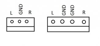
Never meant to have ground switched, just one more hole on ground per each stereo channel so that the braid lead of left and right cables coming off the pair of RCA jacks don't have to share a same ground hole.
A 10-mil trace can pass a lot of current without cooking, This calculator indicates 10-mil 1-oz surface layer trace can do 440mA at 2C rise over 25C ambien with drop of 21mV/in.
The common L and R traces run in parallel to each other over the span of 6 relays (2" perhaps?) and that's where my thought of guarding ground arose. I don't expect it to be a real issue though.
Never meant to have ground switched, just one more hole on ground per each stereo channel so that the braid lead of left and right cables coming off the pair of RCA jacks don't have to share a same ground hole.
Attachments
Never meant to have ground switched, just one more hole on ground per each stereo channel so that the braid lead of left and right cables coming off the pair of RCA jacks don't have to share a same ground hole.
Yes, that's better.
How much better really? I don't see a point, all grounds must be tied at some point so it will have little effect on the actual noise level.
Users would have to crimp on new connectors, the aim was to have a drop-in replacement. If I'm going to make "improvements" to the original layout, the reason should be compelling.
Users would have to crimp on new connectors, the aim was to have a drop-in replacement. If I'm going to make "improvements" to the original layout, the reason should be compelling.
Nice DIY pcb!Hello everyone!
My two cards are completed and just have to make the settings and proceed to testing. They will be positioned one over the other.
Regard's!
Waiting for your test🙂
I have made the settings with a voltage +/-10V (my Borbely - Sulzer) and exactly 5V on TP. The offset voltage output ranges from 0.00 to 0.03 (200mV position on my multimeter) on both cards.
I do not have an oscilloscope and tomorrow I make listening test with my CD player and my amplifier but I have a question.
I can not find the post or we talk about volume control, what value for my test I can use?
Thank you!
I do not have an oscilloscope and tomorrow I make listening test with my CD player and my amplifier but I have a question.
I can not find the post or we talk about volume control, what value for my test I can use?
Thank you!
If you put it after the buffer, use a 10k pot or even 5k. If you put it before, a high resistance pot would be better, such as 50k. 200k could even be used, but I don't know whether it would be better or worse.
Thank you, I have here in my drawers!If you put it after the buffer, use a 10k pot or even 5k. If you put it before, a high resistance pot would be better, such as 50k. 200k could even be used, but I don't know whether it would be better or worse.
How much better really? I don't see a point, all grounds must be tied at some point so it will have little effect on the actual noise level.
Users would have to crimp on new connectors, the aim was to have a drop-in replacement. If I'm going to make "improvements" to the original layout, the reason should be compelling.
A four-pin connector would make no difference electrically but seems a lot easier for wire crimping as one doesn't have to crimp shield braid ends of two wires onto one terminal of the connector. I don't have a DCB1 buffer and will try to find out how they do it.
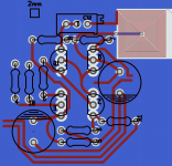
Working on the buffer portion of the PCB. Slowly and messily...
Attachments
Last edited:
Where to place the pot?
Can someone give a definitive answer to the question where to place the pot? Before or after the buffer?
From previous advice on this thread, I've used a 10K log before the buffer. But I do have 47K log or 50K log too to try out after buffer, if that's the better place. In the current position, the 10K log isn't all that sensitive from 6 o'clock (zero volume) to about 9:30 o'clock. I would love a more linear response so that about 9:30 gives regular listening volume (10:30 to 11 o'clock is the current 'regular' position, which I guess, by itself, isn't good or bad).
I guess I will have to try the 47K and 50K before buffer as advised above and hear for myself.
PS: if we use pot after buffer, does it mean that the input impedance of the Kuart will be a constant R8 = 10K?
If you put it after the buffer, use a 10k pot or even 5k. If you put it before, a high resistance pot would be better, such as 50k. 200k could even be used, but I don't know whether it would be better or worse.
Can someone give a definitive answer to the question where to place the pot? Before or after the buffer?
From previous advice on this thread, I've used a 10K log before the buffer. But I do have 47K log or 50K log too to try out after buffer, if that's the better place. In the current position, the 10K log isn't all that sensitive from 6 o'clock (zero volume) to about 9:30 o'clock. I would love a more linear response so that about 9:30 gives regular listening volume (10:30 to 11 o'clock is the current 'regular' position, which I guess, by itself, isn't good or bad).
I guess I will have to try the 47K and 50K before buffer as advised above and hear for myself.
PS: if we use pot after buffer, does it mean that the input impedance of the Kuart will be a constant R8 = 10K?
Last edited:
You could make R8=100k. The reason it's 10k is for DC setups since I was asked for a DC version. However this might make your volume pot uneven.
None of your options can damage anything (unless your system is very sensitive to offset). If I were you, I would try them all by listening. After all, every amp responds to source impedance differently, every source responds to load impedance differently. I can only give rough guidelines on what will lower distortion the most. But low distortion doesn't guarantee good sound.
My suggestions:
For driving a power amp: use the pot before the buffer, so the amp benefits from low source impedance.
For buffering sources needing a light load: Use R8=100k. If driving a power amp, a 200k pot before the buffer may be the best option, if it is statically shielded.
To buffer sources needing constant load impedance: Use a 10k or even 5k pot after the buffer.
Last edited:
The caps are too close, for anyone wanting to zip tie. Which brings up, does one zip tie them together then bend the leads to fit? Long lead length?
Yes, the component spacing is uneven and the transistors could be face to face. Right now I am just working out the possibilities. I will improve spacing once I think I have a viable orientation.
Too bad, it's the only way to have entirely equal fields that I've come up with thus far... I plan to use SEPF caps for this however. Same lead spacing etc.
No reply from Joachim yet. Perhaps you should ask him about bypass caps? He might not pass up a contact from you Keantoken.
No reply from Joachim yet. Perhaps you should ask him about bypass caps? He might not pass up a contact from you Keantoken.
- Home
- Source & Line
- Analog Line Level
- The Kuartlotron - keantoken's simple error-correction superbuffer