Here's Gary Pimms description of how he measured his own CCSs - CCS performance measurments
Was just looking back through this thread. Gary Pimms claims to have measured almost 100 Giga-ohms In a CCS at the low frequency end, is this plausible?
____________________________________
Maybe you will want to try out Richard Jaeger's "High Output Resistance" current source Fig 3(b) to see if it's as good as he says.
(link)
$31 to view....ヽ(*≧ω≦)ノ!!!!!!!
Thanks for the suggestion though! 🙂
Last edited:
Do a DC deltaV/deltaI test & measure to compare to your LF measurements.
I intend to do this. I need to replace the fuse in my 4.5 Digit DMM in order to measure current with sufficient resolution. I tried it with one of my 3.5 digit DMM's and the measurement was at the very limit of the meter, so I'm pretty sure the result was erroneous.
_______________________
(Keithley has a good ebook on measuring low currents)
Udo
I must have missed this comment first time round. Have found the eBook and downloaded it tonight, quite a bit of reading, 239 pages!
Thanks Udo.
Last edited:
The circuit schematic is attached to post 260. Figure 3(b) is the piece on the right, above the "(b)".$31 to view....ヽ(*≧ω≦)ノ!!!!!!!
Thanks for the suggestion though! 🙂
The circuit schematic is attached to post 260. Figure 3(b) is the piece on the right, above the "(b)".
Thanks, looks pretty straightforward, this looks like a type of current mirror. I wasn't sure if it was the right one! 🙂
Presumably Idss of the jfet needs to be above the current that the CCS is used at?
Presumably Idss of the jfet needs to be above the current that the CCS is used at?
You want (Idss >= 20mA); bigger is just fine because the circuit will autoadjust by changing the Vgs bias point to give the 2mA or 5mA current you have chosen. And your tester puts a huge voltage across the current source (about 10V!) so you can use FETs with huge Idss if you wish. Shoot even the J105 with Idss=500mA would work. Of course you open the door to many more possible partnumbers if you allow yourself to use NJFETs in surface mount packages.

Whilst doing some research into other types of current sources, I found this oddity- a radioactive current source:
http://tubedata.milbert.com/sheets/127/c/CH1027.pdf
http://tubedata.milbert.com/sheets/127/c/CH1027.pdf
Whilst doing some research into other types of current sources, I found this oddity- a radioactive current source:
that's neat!
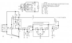
As suggested split the amplifier into 2 20db stages, new schematic attached.
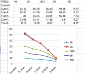
Results of 2 transistor CCS at different DC currents, see attached.
Would seem to confirm that current source impedance is inversely proportional to the DC current.
Gordon.
Results of 2 transistor CCS at different DC currents, see attached.
Would seem to confirm that current source impedance is inversely proportional to the DC current.
Gordon.
Attachments
Last edited:
As suggested split the amplifier into 2 20db stages, new schematic attached.
Results of 2 transistor CCS at different DC currents, see attached.
Would seem to confirm that current source impedance is inversely proportional to the DC current.
Gordon.
Which transistors did you use for the CCS?
Which transistors did you use for the CCS?
Both bc549c with beta around 530.
After you finish measuring impedance-vs-frequency for your 2-BJT current source circuit, you may decide you want to measure a few other circuit designs for current sources.
I've been reading the new book by Arto Kolinummi (LINK) and as luck would have it, he explores this very thing on pages 124-135.
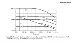
The good news is, he presents several different circuit topologies that can serve as inspirations for your own design work. The possibly not so good news is, he extracts their output impedance from circuit simulations, rather than physical measurements of laboratory prototypes. Still, I imagine that the circuit which simulates "best" (highest output impedance) probably also measures "best" with physical devices, and the circuit which simulates "worst" probably also measures "worst". He appears to choose his SPICE simulation models very carefully.
For what it's worth, here is one of his figures. When each of the six current sources is delivering 5 milliamps, he finds two of them have Zout = 10^9 ohms (1000 Megohms), and another has Zout = 10^12 ohms (1 Teraohm, a million Megohms). In simulation.
{notice that the top curve has slope greater than 20dB/decade, suggesting two or more poles are present}
_
I've been reading the new book by Arto Kolinummi (LINK) and as luck would have it, he explores this very thing on pages 124-135.
The good news is, he presents several different circuit topologies that can serve as inspirations for your own design work. The possibly not so good news is, he extracts their output impedance from circuit simulations, rather than physical measurements of laboratory prototypes. Still, I imagine that the circuit which simulates "best" (highest output impedance) probably also measures "best" with physical devices, and the circuit which simulates "worst" probably also measures "worst". He appears to choose his SPICE simulation models very carefully.
For what it's worth, here is one of his figures. When each of the six current sources is delivering 5 milliamps, he finds two of them have Zout = 10^9 ohms (1000 Megohms), and another has Zout = 10^12 ohms (1 Teraohm, a million Megohms). In simulation.
{notice that the top curve has slope greater than 20dB/decade, suggesting two or more poles are present}
_
Attachments
Only a & b fit with my original guesstimate of around 300kohms.
Andrew, was your 300k estimate for a one transistor current source?
Mark, would it be possible to share the details of the current sources that your graph refers to?
Gordon.
I don't think that simulation gives us new insight here. The models are not good enough. At output impedances > 10 MOhm a picofarad is important.
For example 1 pF at 10 KHz has 16 Mohm impedance.
It is not possible to build a current source with 1 TOhm at audio frequencies - forgett about the book.
For the last circuit i get 4.6 MOhm @ 1 kHz and 5 mA and 4.2 MOhm @ 10khz.
The output amplifier has an error of 13% at 1 kHz due to the 50 Hz notch filter by the way.
The output amplifier has an error of 13% at 1 kHz due to the 50 Hz notch filter by the way.
I measured the response of the amplifier / notch filter and substituted the measured gain into the formula for impedance. Yes I was surprised how much attenuation the notch filter yielded so far from its center frequency, is this a flaw of this particular type of notch filter ( Hall notch filter ) rather than the usual twin tee type?
Gordon.
P.S. Regarding simulation results: Do the transistor models not include parasitic capacitances, considering the suggested impedances from the simulation results it doesn't look like it. I only have a very basic simulator on my android tablet ( My PC is broken ) and I got pretty similar results to my experiment for a 500 microamp ccs, but for the 5mA ccs the result was considerably higher than in the experiment. Impedance falls with increasing test frequency so the transistor models must include capacitive elements, however transistor parameters that can be varied in the simulator are pretty limited and there is no provision to adjust capacitive parameters, strangely though it allows you to do that with diodes!
If you're interested, here it is ( It runs on Apple OS, Android and Google Chrome ):
EveryCircuit
I (and i think many others) would be really interested to see more measurement results with different transistors and configurations.
Please try out the measurement with some high valued resistors to increase confidence in the results!
Please try out the measurement with some high valued resistors to increase confidence in the results!
I (and i think many others) would be really interested to see more measurement results with different transistors and configurations.
Please try out the measurement with some high valued resistors to increase confidence in the results!
I forgot to mention that the last time I took measurements, i measured a 50 Megohm resistor and the error was only 2~3%.
Gordon.
- Status
- Not open for further replies.
- Home
- Amplifiers
- Solid State
- How do you calculate impedance of a current source?