Well--Who Cares, A, AB, B, C These are just letters so who really cares....!
What should be more important--is addressing the distortion that occurs when grid-current is drawn.
Suggest a MOSFET Grid Driver for the output pair, or redesign to remove the coupling-caps and use the transformer secondaries direct....
Exactly! BallPencil needs to address the effects of grid current. He can do that by getting rid of the grid capacitors and adopting series biasing like Koonw has suggested more than once now. Seems like you are the only one who listened.
Just in case more reinforcement is needed...
I checked the Class definitions in Fundamentals of Engineering Electronics, William C Dow (pages 303 & 304). The are essentially the same as Reich, except Dow uses the word about instead of approximately. It is interesting that he follow the definition of Class B with a diagram of typical Class B showing grid current on postive peaks
I checked the Class definitions in Fundamentals of Engineering Electronics, William C Dow (pages 303 & 304). The are essentially the same as Reich, except Dow uses the word about instead of approximately. It is interesting that he follow the definition of Class B with a diagram of typical Class B showing grid current on postive peaks
The 6C33C doesn't need positive grid voltage (relative to cathode) to get the anode current up to 2.5A.
Chris
Really? Extrapolate the zero bias line on the published anode curves up to 2.5 amp and see where it lies - it lies to the left of 130V anode voltage. Hence postive grid voltage required.
Assuming of course the the tube can actually deliver 2.5 amp over a period of time. That's well outside ratings. I have my doubts. Over time its' likely to need increasingly more positive grid volts.
I don't think the extrapolation of the published curves up to 2.5A is very reliable. My own experience with several OTLs using the 6C33C is that positive grid voltage is not needed to reach 2.5A. I'm away from home where my OTL amplifies are right now, otherwise I'd just stick a scope onto one of them to check the grid-to-cathode voltage that achieves 2.5A.
If it were the case that it needed positive grid voltage to achieve 2.5A then that would mean every OTL using a pair of 6C33C to produce 25W would need drivers capable of supplying grid current, and I think there is ample evidence that some of the common designs out there achieve 25W without being able to drive with grid current.
Maybe someone who has access to a 6C33C OTL could chime in here with a measurement? It's a very simple one to do.
I've been running 6C33C OTLs for quite a few years now, and I've not noticed any significant degradation in performance. Of course, one is typically not listening to a steady 25W sinewave for hour after hour, which is probably why one gets away with a bit of intermittent "abuse" of the tubes! They are pretty rugged things, in my experience.
Chris

According to my ltspice simulation both drawn grid current except direct coupled one is drawing a little heavier 🙂
Attachments
Last edited:
I don't think the extrapolation of the published curves up to 2.5A is very reliable.
I agree that extrapolation is usually unwise. But the curves only go to 1 Amp so what are we to do?
The thing is - which way are the curves going to bend? Towards a more positive grid or away from a more positive grid? I'll put my money of the former. I cannot think of any triode tube mechanism that would bend the anode curves to the right. Even an 'ideal" tube follows a V^3/2 law - bending to the left.
Any issue with insufficient emission, grid structure design, etc is going to increase the bend to the left (ie more postive grid).
An actual measurement would be nice. Much better than a dodgy SPICE simulation done with a tube model of unknown providence.cnpope said:
"Maybe someone who has access to a 6C33C OTL could chime in here with a measurement? It's a very simple one to do."
I wish I had a dollar for all the amateurs misled by SPICE. I'd be stinking filthy rich by now. Don't get me wrong - SPICE is a very good tool in the hands of an expert.
Last edited:
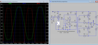
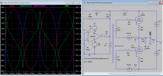
According to my ltspice simulation both drawn grid current except transformer coupled one is drawing a little heavier 🙂
You've seriously overdriven it though. It's clipping. BallPencil might not regard that as fair.
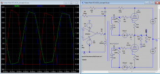
OK. Here is a better one. The thing is I need to reconfigure the inductance so that it is capable of over-drive needed for grid current drawn. The snapshot show only the inter-stage transformer, while the conventional cap resistor driver may not be able to overdrive as driver itself is clipping so there is nothing much to worry I guess. This is the thing about using OpAmp that does not clip before output tubes do. Still the grid current overdrawn is not that much, unless it's driven into! 🙂
Attachments
Last edited:
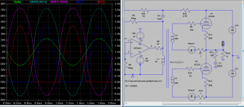
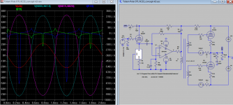
It's not unexpected that a) raising the HT from 150 V to 180V per side (which increases the current for any given grid voltage), b) raising the bias from 47V to 70V, and c) getting rid of the grid capacitors, as you have done, would make it work a lot better.
But what IS the actual magnitude of the expected grid current in your sim?
But what IS the actual magnitude of the expected grid current in your sim?
It's not unexpected that a) raising the HT from 150 V to 180V per side (which increases the current for any given grid voltage), b) raising the bias from 47V to 70V, and c) getting rid of the grid capacitors, as you have done, would make it work a lot better.
But what IS the actual magnitude of the expected grid current in your sim?
Ok, I think so, sonic wise not too sure though.
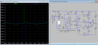
50uA. Please note the difference of 0.495V to 0.5V to input signal, seeing huge spike go up..just before clipping. not sure what it is at the moment.
Attachments

Last edited:
It is. It's an AB1 circuit. Operating angle is not 180 degrees. It's also not 181 degrees. 😀 .
Thanks SY, just the person i was hoping to chime-in. Unfortunately, i don't think you would bother to explain why my amp is class AB1. That's ok, i am still here.
Keit, this is fun! Let's go again!
I realize we are debating on two points:
1. Whether my amp is Class AB or class B
2. Whether the output tubes are pulling grid current
Let's address the first point.
That transistor amp is a Class B amp. Calling typical solid state amps AB is a common misconception. They are Class B because each output transistor is cut off for approximately half a cycle. That is precisely the definition of Class B. And it makes cross over distortion an issue that the design engineer MUST address.
Here is one actual sample of such amplifier.
60-80W Power Amplifier
Now, if you can be bothered to read the article, you can see that 60W amp's output transistors are targeted to be biased at 50-100mA and the designer clearly say that it's class AB. He even mention to avoid biasing less than 20mA as that is when distortion starts to be noticeable. So does it mean it's class B when we bias at 19mA? No, it is still class AB.
In the actual words of the designer:
VR1 is used to set the quiescent current, and normally this will be about 50-100mA. The amp will work happily at lower current, but the distortion starts to be noticeable (on a distortion meter monitored by an oscilloscope) at less than around 20mA (the recommended minimum quiescent current).
You can't say "approximately half a cycle" because that approximate can be the difference between class AB or class B.
Class A is where both output devices are conducting for the full 360deg of the cycle
Class B is where both output devices are conducting for exactly 180deg of the cycle
Class AB is where both output devices are conducting between more than 180deg to less than 360deg.. So, if the devices are conducting for even 181 deg of the cycle, it is class AB because for the small window of 2deg (1degx2), both devices are conducting at the same time. It may still has audible crossover distortion with only 2 deg of concurrent conduction window, but it is class AB by definition.
What happens is both devices are conducting for less than 180deg? This is class C.
See why you can't say approximately? Because 1 deg can be the difference between class AB or class B.
We can't even say an amplifier being class A if the devices are conducting for only 359.99deg of the cycle because for the remaining 0.01 deg, only one active device is conducting. This makes it class AB.
Now, let's return back to this graph that you have ignored:
All the words on this graph are copied from your actual post, except the words pointed by the arrow. Those are mine.
An externally hosted image should be here but it was not working when we last tested it.
Can you see that each output triode are still conducting for more than half of the signal cycle? Hence, it is class AB.
Here it is redrawn
An externally hosted image should be here but it was not working when we last tested it.
Is it clear now, why my amp is class AB?
Yes, you are correct on the calculation. I was mixing up the calculation with single-ended amp. But i am adamant that for output power less than 0.63W, my amp is in class A. Anything more than that is Class AB.In the region where both tubes are conducting, an approx calculation is this: As one tube goes down 200 mA, the other goes up 200 mA. So the peak output to the load is 400 mA. Power depends on the RMS value however. So the load power is (0.4 x 0.7)^2 x 8 ie 0.63W.
Using Olympic Relay Race with two runners as analogy, here is amplifier class explained.
Class A = Both runners are holding on to the stick for the whole track. They both start and finish at the same spot. Seems silly, hahaha..
Class AB = this is the classic relay race method. The first runner slows down while he hands over the stick to the second runner who is accelerating. During this transition, both runners are holding on to the stick.
Class B = there is no point at all in the race where both runners are holding on to the stick at the same time. Just as when the first runner lets go of the stick, the second runner starts to touch the stick.
Class C = first runner throws the stick to the second runner and there is a point in mid air where no one is touching the stick. Of course, this means they are both disqualified.
Addressing the second point (Whether the output tubes are pulling grid current), will be on the next post. Stay tuned..
Unfortunately, i don't think you would bother to explain why my amp is class AB1.
Sure I would. The operating angle is significantly higher than 180 degrees and it doesn't draw grid current until you clip it. Really, it's no more complicated than that.
cnpope's posts are very much worth reading here, since he has actually built and used amps with those tubes.
Now let's address the second point, whether my amp draws grid current. I am on the side saying that it's not. You are saying it is.
I never said my amp puts out 2.5A. My 6C33C model gives peak current of 2A at Vgk =0v. I clearly said that on the first post. If you check again below graph, peak current is even less at 1.8A. This is because i am still not touching Vgk =0v. I am still below that where Vgk is negative, or no grid current teritory as we know it.
Now, 1.8A to 8R speaker means 13 watts which translates to voltage swing of approx 15 volts. First, let me assure you that the voltages shown are at the correct Node and that although i am newbie, i am not showing the wrong graph. Here is the grid voltage of the top tube at N007
Here is the cathode voltage at N010.
Here is the graph again..
So, is it clear now why there is no grid current?
Just in case you are curious, here is the bottom tube cathode voltage vs grid voltage with respect to ground.
@AlastairE
Nothing to address as there is no grid current being drawn. period.
Do you have a MOSFET Grid Driver on your Inverted Futterman OTL amp? No right? And yet it sounds just fine, doesn't it? Because my Futterman schematic shown earlier and yours are fundamentally the same. Keit is saying that it is also pulling grid current. Just as a reminder, here is your amp.
and here is mine.
It cannot be the top tube drive, as on +Ve peaks you have it putting out 2.5 A. 2.5 A into 8 ohms equates to a cathode voltage 20 V. 6C33C curves only go to 1A but by extrapolation to get 2.5 A anode current at Va 130V, the grid must be positive (by about 12 to 14V).
I never said my amp puts out 2.5A. My 6C33C model gives peak current of 2A at Vgk =0v. I clearly said that on the first post. If you check again below graph, peak current is even less at 1.8A. This is because i am still not touching Vgk =0v. I am still below that where Vgk is negative, or no grid current teritory as we know it.
An externally hosted image should be here but it was not working when we last tested it.
Now, 1.8A to 8R speaker means 13 watts which translates to voltage swing of approx 15 volts. First, let me assure you that the voltages shown are at the correct Node and that although i am newbie, i am not showing the wrong graph. Here is the grid voltage of the top tube at N007
An externally hosted image should be here but it was not working when we last tested it.
Here is the cathode voltage at N010.
An externally hosted image should be here but it was not working when we last tested it.
Here is the graph again..
An externally hosted image should be here but it was not working when we last tested it.
So, is it clear now why there is no grid current?
Ask and you shall receive.One would have expected the grid drive graph to be with respect to cathode - that is the common convention.
An externally hosted image should be here but it was not working when we last tested it.
Just in case you are curious, here is the bottom tube cathode voltage vs grid voltage with respect to ground.
An externally hosted image should be here but it was not working when we last tested it.
@AlastairE
What should be more important--is addressing the distortion that occurs when grid-current is drawn.
Suggest a MOSFET Grid Driver for the output pair, or redesign to remove the coupling-caps and use the transformer secondaries direct....
Nothing to address as there is no grid current being drawn. period.
Do you have a MOSFET Grid Driver on your Inverted Futterman OTL amp? No right? And yet it sounds just fine, doesn't it? Because my Futterman schematic shown earlier and yours are fundamentally the same. Keit is saying that it is also pulling grid current. Just as a reminder, here is your amp.
An externally hosted image should be here but it was not working when we last tested it.
and here is mine.
An externally hosted image should be here but it was not working when we last tested it.
Some additional info.. Here is the peak current given by my 6C33C model when Vgk is close to 0v.
An externally hosted image should be here but it was not working when we last tested it.
But what IS the actual magnitude of the expected grid current in your sim?
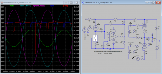
Here are 3 snapshots of grid current wave forms, below zero (<-70V and above zero (>-70V), Again I reconfigured the inductance for over drive to happen. Please help me to decide if this is for real, thank.
Attachments
Hah! Havent seen that diagram for a while!
Ballpencil--
Concerning that particular OTL. It was an attempt at autobias in the output stage and does not (as quoted in the diagram) produce much power, but had advantage of just building, installing any old 6C33 unmatched and would work. It didn't Need a lot of power to for the application I was using it.
Fixed-bias two 6C33C tube Futterman can easily do 20 odd Watts measured across 8 ohm non-inductive, and not have to resort to grid-current, but in experiments I did way back then the topology does benefit from a stiff drive capable of supplying into grid positive territory--It just sounded better, the 6C33C with its huge cathodes, grids and plates does have considerable Miller....
An interesting thing I did find--and will possibly transfer to other similar design OTL's is that speaker-impedance (Not being a flat 8 ohms at audio range) will affect the actual power and particularly the Perceived Sound Level. A straight 8 ohm non-inductive load indicated only 5W or so as I recall in that original design of mine--But Sounded like 20 odd Watts due to the higher than 8 ohm Reactance at audio-band frequencies, being an easier load to drive....
--I certainly couldn't keep the amp near its full output, as neighbours would complain....
One of the joys of living in an apartment........
Those 50 uA currents look more like internal grid capacitance (with Miller C) currents. If you mod the tube model to zero grid capacitances, they will probably go away.
This class aB versus class B interpretation stuff probably stems from solid state designers (the marketers actually) re-defining class B so they would be saved by a hair. Marketing "Watts" seem to have the same problems these days. I think the original tube class definitions, as Keit pointed out, would put OTL amps solidly into the class B range, in spirit. Otherwise, the never ending uA conduction tail of tubes would make everything class A.
Tubes generally drop down progressively toward linear Vgrid to Ip operation as they get extended to higher current, then they curve over to less than linear curves as cathode saturation sets in.
The original idea of "SE sound from P-P operation" using the "feedback triode" was intended for use with an amplifier that would have "clean" (to the ears at least) distortion when using ordinary R divider feedback of similar attenuation. Then the feedback tube would just add its coloration to the forward gain function. The distortion spectra presented earlier for the OTL amp doesn't look much like what one would expect for a single tube operated under CCS conditions. Although the Op Amp may be putting in heroic effort at distortion cleanup, it doesn't seen to be quite making it here. But an interesting attempt at least. Probably would have to use a class A tube amp to succeed without using Mega N Fdbk.
I'm puzzled by Keit's assertion that a class B amp would almost always draw grid current. Class A operation typically runs the grids well below 0V grid voltage (over Op range), to avoid over dissipation of the tube plates. Class AB or class B would have much more current available when run to just below 0V on the grids, so should be able to put out more power than class A, without necessarily going into grid current.
Edit: included 300B gm curves, see page 5, for trend at higher current
Attachments
Last edited:
Keit, this is fun! Let's go again!
I realize we are debating on two points:
1. Whether my amp is Class AB or class B
2. Whether the output tubes are pulling grid current
Let's address the first point.
Here is one actual sample of such amplifier.
60-80W Power Amplifier
Now, if you can be bothered to read the article, you can see that 60W amp's output transistors are targeted to be biased at 50-100mA and the designer clearly say that it's class AB. He even mention to avoid biasing less than 20mA as that is when distortion starts to be noticeable. So does it mean it's class B when we bias at 19mA? No, it is still class AB.
You can find all sorts of stuff on the WWW. Just because some hobbyist has a website doesn't mean it 100% right.
I already acknowedged that some people mis-apply the definitions to solid state amps.
Nope. You're wrong. That 181 deg amp is Class B.Class A is where both output devices are conducting for the full 360deg of the cycle
Class B is where both output devices are conducting for exactly 180deg of the cycle
Class AB is where both output devices are conducting between more than 180deg to less than 360deg.. So, if the devices are conducting for even 181 deg of the cycle, it is class AB because for the small window of 2deg (1degx2), both devices are conducting at the same time.
You can't just use your own definitions. Communication and understanding comes from adhering to language conventions.
In previous posts I quoted from standard well known textbooks on what is A, AB, and B. They all use words like approximately, about.
They aren't my definitions. I didn't write those books.
A lot of tube PA amplifiers (racecourse & stadium amplifiers etc) were described in their service manuals as Class B. They all had a small standing current.
With few exceptions tube AM broadcast transmitters used high power audio amplifiers to modulate the RF final. They were always described by their makers as Class B. And they all had a small standing current to reduce cross-over distortion. There is an optimum standaing current. Too much or too little, you get cross-over distortion.
I gues its important for you that your amp is called Clas AB is it is well known that AB1 gives a nicer sound than B.
However, you can assert its AB all you like. The fact is, its a Class B amp, becuase the tubes are cut off for about hlaf a cycle and it will sound like one.
Yes, you are correct on the calculation. I was mixing up the calculation with single-ended amp. But i am adamant that for output power less than 0.63W, my amp is in class A. Anything more than that is Class AB.
Go get a copy of the Radiotron Designer's Handbook, Reich, or Dow, or any other recgonised textbook from the tube era. Not some dodgy website.
You'll find the Class A, AB, B is defined just as I said in my posts #57 and #41. In those posts I copied the words from the books - they are not my words.
If you call your amp Class AB, which isn't right, you can only fool yourself.
Now let's address the second point, whether my amp draws grid current. I am on the side saying that it's not. You are saying it is.
All your graphs and words are just so much woffle.
Its very simple. You have a standing grid bias of 47V. You have a grid signal excursion of 122V. I got those figures from your post #29.
Since 122V pk-pk is 61V pk, the grids are driven postive by the amount 61 - 27 V. If the grid goes postive wrt the cathode, you have grid current. End of story really. But there is confirmation.
The 2.5 A peak figure comes from your estimate of maximum output in your Post #1. The fact that you subsequent graphs show conduction for approx half a cycle at a much lower peak output of 1.8A just re-inforces that your amp is a Class B amp.
Koonw in his post #76 shows that grid current just begins to flow at max output. However, in his simulation, he took a number of measures that considerably reduce grid current - measures that you haven't tried:-
1. Increase of HT from +,-130V to +,- 180V
2. Increas in bias from 47V to 70V
3. Removal of the grid capacitors and biasing in series per normal and necesary Class B practice.
So if Koonw found there is grid current, your amp, without these important measures, is going to pull lots of grid current.
- Status
- Not open for further replies.
- Home
- Amplifiers
- Tubes / Valves
- Another Approach to Totem Pole OTL Amplifier