yup, i can't prove it now because you edited your earlier posts...but i idid recall you said it early on...
What nonsense are you coming at?
It is not possible for me to edit earlier posts. We get a limitted opportunity to edit our last post for 10 minutes or so, then its locked. The Edit button doesn't appear.
yes you have 30 minutes and the post gets locked.....did i say you edited in the last 10 minutes....? it is what you said in your earlier post that i remember well, then today i remembered the posting by nanana to the effect that for common cathodes the load did not necessarily had to be connected to the plate....anyway i am glad that you acknowledged the upper triode as such....that is all that matters...kindly ignore my non-sense...
Your graph shows it swinging between +14V and -108V. Total swing 122V.
That 122V pk-pk swing, together with the 47V standing bias is all we need. Those two figures mean grid current (which pushes the whole waveform negative).
If you think your simulation shows no grid currrent than your simulation is faulty (as I said before that can be an outcome of how SPICE works), or you have misinterpreted what its telling you.
It doesn't matter how many times you keep posting graphs, a 122V swing with 47 V bias means grid current. Any time you have a grid swing greater than twice the bias, and you have a grid coupling capacitor, you have grid current. Simple 1st year algebra fer chist's sake.
Ballpencil already addressed this. The 122V pk-pk swing you are looking at is the voltage on the grid, relative to ground. But the voltage on the cathode is swinging too. When the grid voltage goes in the positive direction the tube conducts more, and the cathode voltage (relative to ground) goes in the positive direction too. The potential difference between grid and cathode, Vgk, is always staying negative, as seen in the simulation.
The mere fact that the pk-pk swing of the grid voltage relative to ground exceeds twice the bias voltage does not mean that Vgk has to be going positive. The SPICE simulation is perfectly logically valid in what it is showing, with Vgk always staying negative.
A separate question is whether the SPICE model of the 6C33C is trustworthy in the regime where the anode current is getting very large and off the scale shown in the tube data sheet. In particular, there is the question of how large the anode current can be while keeing Vgk non-positive. This would be best settled by experiments, which as I mentioned before would be very easy to do if one has access to a 6C33C OTL. But my impression and experience, and I think the experience also of other people who have built OTLs based on the 6C33C, is that the 2.5A anode current, corresponding to the case of 25W into 8 ohms, is attained while Vgk stays non-positive.
Chris
Last edited:
I wast just about to reply regarding the grid swing, but cnpope beat me to it.
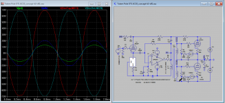
For the upper valve (from graphs in post 74):
grid swing 115v pp
cathode swing 30v pp, this is due to the output voltage to the speaker
vgk = 115-30 = 85. no grid current as this is less than twice the bias of 47V
For the lower valve:
grid swing 86v pp
cathode swing 1v pp due to cathode resistor
vgk =85.
Please try changing the K coupling factor to something like 0.99985 and see what happens, I am getting some oscillations, do you?50uA. Please note the difference of 0.495V to 0.5V to input signal, seeing huge spike go up..just before clipping. not sure what it is at the moment.
How about the 100uF's on the secondary windings?This schematic show how to avoid grid coupling capacitors for output power tubes .
Ballpencil already addressed this. The 122V pk-pk swing you are looking at is the voltage on the grid, relative to ground. But the voltage on the cathode is swinging too. When the grid voltage goes in the positive direction the tube conducts more, and the cathode voltage (relative to ground) goes in the positive direction too. The potential difference between grid and cathode, Vgk, is always staying negative, as seen in the simulation.
And as I pointed out long ago, there is a rat in there somewhere. BallPencil's first graph in his post #29 shows a grid swing of 122V. His second graph in post #29 shows tube current peaking at 1.8V. With an 8 ohm load, that means the cathode only peaks at 14V. So if the first plot shows the upper triode grid wrt earth, the true grid-cathode swing is 122-14 ie 108V. That's still more than twice the grid bias, so there's still grid current.
Initially I assumed it was plot of grid-cathode voltage, because that would agree with the 6C33C extrapolated curves, and because its the convention to do so.
I asked BallPencil to clarify just what is depicted in the plot but he failed to do so.
But it matters not. Even assuming the plot is indeed wrt earth, there is still grid current.
You have not explained away Koonw's plots. He took some good measures that significantly reduce the susceptability to grid current, and he still got grid current:-
1) He increased the HT voltage from 150V to 180V, which increased the anode current for any given grid voltage;
2) He increased the bias from 47 V to 70V, increasing the signal swing required to get grid current from 94V to 140V.
Since he did still get grid current, BallPencils version MUST go into grid current at a much lower signal level (roughly about half) than BallPencil's and draw a lot more grid current.
That's all certainly very true.A separate question is whether the SPICE model of the 6C33C is trustworthy in the regime where the anode current is getting very large and off the scale shown in the tube data sheet. In particular, there is the question of how large the anode current can be while keeing Vgk non-positive. This would be best settled by experiments, which as I mentioned before would be very easy to do if one has access to a 6C33C OTL.
How about the 100uF's on the secondary windings?[/QUOTE said:----------------------------------------------------------------
Those two 100uF can not introduce blocking distortion as conventional coupling capacitors does .
How about the 100uF's on the secondary windings?
Good point. They'll get charged up by the grid current just the same as BallPencils grid capacitors.
In BallPencil's, the grid circuit time constant is 220nF x 220Kohm = 48 milliseconds. Thats more than enough to make large signal recovery terribel to listen to.
In the other circuit, the time constant is 4.3 Kohm x 100uF = 430 milliseconds. Half a second of post-drum beat paralysis, you'd think. No doubt BallPencil will be pleased that this is one aspect where he appears to have done a lot better than someone else.
However, there are three 6C33C's in parallel each side. So the grid swing required is (taking into account the lower HT; all other things equal) only about half of that in BallPencil's circuit. So, about 60V swing with 28V to 39V bias. Grid current not going to be a real problem then.
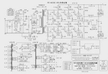
That Chinese circuit is actually quite good. It has a number of subtle design features.
Last edited:
Bezdz is the company that did the design, I believe the founders were all red army aka PLA signal corp. guys, you can check out their website, they have a bunch of tube amp kits with interesting design features and quite a bit of surplus military parts for sale.That Chinese circuit is actually quite good. It has a number of subtle design features.
Bezdz is the company that did the design, I believe the founders were all red army aka PLA signal corp. guys, you can check out their website, they have a bunch of tube amp kits with interesting design features and quite a bit of surplus military parts for sale.
Its in Chinese. No good to me - I can't read Chinese.
However the english version is at http://www.bezdz.com/engindex.html
Last edited:
And as I pointed out long ago, there is a rat in there somewhere. BallPencil's first graph in his post #29 shows a grid swing of 122V. His second graph in post #29 shows tube current peaking at 1.8V. With an 8 ohm load, that means the cathode only peaks at 14V. So if the first plot shows the upper triode grid wrt earth, the true grid-cathode swing is 122-14 ie 108V. That's still more than twice the grid bias, so there's still grid current.
Post #29 shows grid swing (w.r.t earth) of 122v p-p and cathode swing of about 31v p-p for a Vgk of 91v p-p. This is entirely consistent with a peak current of 1.8A into 8.5 ohms (allowing for 0.5 ohm cathode resistor) and still no grid current. You subtracted peak cathode voltage from peak-to-peak grid voltage.
It was previously mentioned that the low levels of grid current seen in Koonw's plots may be due to charging of the triode input capacitance.
That said, OTL's hold no appeal to me except for headphone amplifiers where the higher impedance and lower power requirement makes life easier, even though they are still horribly inefficient.
Post #29 shows grid swing (w.r.t earth) of 122v p-p and cathode swing of about 31v p-p for a Vgk of 91v p-p. This is entirely consistent with a peak current of 1.8A into 8.5 ohms (allowing for 0.5 ohm cathode resistor) and still no grid current. You subtracted peak cathode voltage from peak-to-peak grid voltage.
Oops. I did make that mistake.
Yes, I noticed that. But I didn't believe it. If it was due to tube capacitance, the current would be sine. It's not, it's very peaky just as you would expect for grid current.It was previously mentioned that the low levels of grid current seen in Koonw's plots may be due to charging of the triode input capacitance.
From the 6C33C data, Cgk = 30 Pf, Cga = 31 pf. Taking into account miller effect, at KoonW's test frequency of 1 KHz, the input impedance is 1.4 Megohm. So the current, with his grid swing of 70V peak, should be around 70 /1.4 = 32 uA peak. He got 300 uA in one tube and 400 uA in the other.
Nope, the capacitance theory advanced by Smoking Amp is shot down.
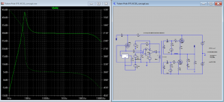
Please try changing the K coupling factor to something like 0.99985 and see what happens, I am getting some oscillations, do you?
How about the 100uF's on the secondary windings?
I did get oscillation before when K is other 1. However as I inserted 20 ohms in the inductor data entry (no shown in schematic), this is what I get. See attached 6C33C grid current-df-k0.99985-1.png
100uF is just too big, it takes too long to process..
The other snapshots are something you maybe interested as to when the grid start to draw current. Does it start to draw current as soon as driven into clipping? Ans: Yes and No. If the output tube clipped earlier than driver then Yes, and if driver clipped earlier then NO. To do that I change OpAmp supply from 18V (clipping) to 24V (no clipping). As soon as you get over zero bias point you got grid "extra current" spike. That is what the sim said.
Thank you for your input I try to incorporate your idea as much as possible as discussions go along.
Attachments
Last edited:
Koonw,
What may be worthwile for BallPencil, is to scale the HT back to his +,-150V, which will require more grid drive for the same output, and put the bias voltage back to his 47V. What is the magnitude of the grid current then?
I suggest you revert to your earlier cicuit with teh bais supply in series with the transformer secondaries and no capacitors.
Koonw,
What may be worthwile for BallPencil, is to scale the HT back to his +,-150V, which will require more grid drive for the same output, and put the bias voltage back to his 47V. What is the magnitude of the grid current then?
I suggest you revert to your earlier cicuit with teh bais supply in series with the transformer secondaries and no capacitors.
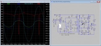
Ok ok, here is the snapshot, it's kind of critical as I try to take the first point grid current spike appeared so it bias is about -47V.
Attachments


Last edited:
Koonw,
Thank you. Grid current peaking to close to 700 uA at a grid drive of +,-49V.
Clearly, grid current is significant in BallPencil's circuit.
If you were to put his 220nF grid caps and his 220K resistors back in, the grid current will do its usuall thing and shift the whole grid drive waveform negative, until the energy dissipated by the DC in the 220K resistors just balances the energy supplied by the grids. This increases the working bias beyond the bias supply, by charging the caps.
And, clearly, tube capacitancies have nothing to do with it.
Oops. I did make that mistake.
So, have we finally established that Vgk remains negative for the full cycle?
Thank you. Grid current peaking to close to 700 uA at a grid drive of +,-49V.
Clearly, grid current is significant in BallPencil's circuit.
Sure it's significant because he's exceeding the bias voltage of 47V by 2 volts. Keep the grid drive below 47v as what i did and see what happens.
edit: just realized he did it on the second capture.. so, 25 microamps. Not so significant now, is it?
Anyway, i should have pointed out the reasons for some of the values on my amp, hoping we can have some restrictions set before we go about modifying it too far from the basic.
1. +/-150V is chosen with the consideration this is the value we get after rectifying 110+110VAC transformer, with some spare for voltage drop in the mains line. I design my amp so that i can use simple isolation transformer which usually comes with 110VAC secondary tap. This translates to economy.
2. The upper tube should be able to be biased with servo and utilize the lower -150v supply with some voltage divider. This avoids having an extra supply just for bias purpose. I am not sure if this can be translated to DC coupling from the secondary winding to the grid, at least to reduce poles in the circuit.
3. The lower tube will also be biased with voltage multiplier from the original
110+110VAC transformer. Again, avoiding extra power supply just for bias purpose.
4. The inductance values on the interstage transformers are chosen with the consideration that these are what you get with small toroidal mains transformer with 110+110V primary and 24V secondary. This thing cost you only 16 USD with free shipping on Ebay. Member shoog here has used it for this purpose in his 6AS7 PP amp. Basically, this translates to: don't change the inductance values.
5. The chip amp on the input and the DC servo should be powered from the same low voltage supply = +/- 18V. I would even prefer if it can be power by +/- 12V supply so that i can use it to power the heater as well but i think this is too close to clipping the op-amp.
6. All tubes should be able to be heated by using ground-level power supply. This avoids the trouble of creating heater elevation. Good thing 6C33C has Vhk max of 300V. This is a very large breathing room that means both upper and lower tube can be from the same tube envelope, power by grounded 12.6V heater supply.
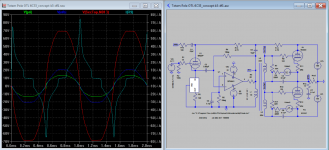
I modified the original circuit with DC servo and end up with below updated one.
I added 0.5R series resistance (a reasonable value, no?) on The transformer primary (L1) and reduce R3 and R4 to 22k and this simulates to around 0.3mA standing current on the primary. Small enough that we can ignore it. Not sure if this is the same in the actual circuit later.
I still need to heed jerluwoo's advice to add maximum reflected impedance but i don't know how to calculate the resistor value, help? jerluwoo uses 47R resistors across the transformer secondary. I think this is crazy low so how did he end up with this value? Also, 47R equals 8Amps of drive current from the Op-amp. This is crazy.
An externally hosted image should be here but it was not working when we last tested it.
Last edited:
Are you sure you want to stick to your front end?
Why are you not following Tube Cad? Please explain and compare why are referring to it, you maybe going too far in the first place, not offense intend.
Why are you not following Tube Cad? Please explain and compare why are referring to it, you maybe going too far in the first place, not offense intend.
Attachments
Last edited:
+1, before trying to re-invent the wheel, learn the pitfalls of the Futterman/Rozenblit designs as koonw suggested, take a look at TubeCad for starters. If this is just an academic exercise, then go hog wild with your innovations.😀Are you sure you want to stick to your front end?
Why are you not following Tube Cad? Please explain and compare why are referring to it, you maybe going too far in the first place, not offense intend.
- Status
- Not open for further replies.
- Home
- Amplifiers
- Tubes / Valves
- Another Approach to Totem Pole OTL Amplifier