It IS a clear cut case. Your amp operates as Class B.
Here is the definition from the well respected Radiotron Designer's Handbook - a stanrd reference in the English speaking world:-
Class A: A Class A amplifier is an amplifier in which the grid bias and alternating grid voltages are such that the plate current of the output valve or valves flows at all times. (Sect 5 i B on page 572)
Class B: A Class AB amplifier is an amplifier in which the grid bias and alternating grid voltages are such that the plate current of a specific valve flows for appreciatively more than half of the input cycle.
An AB amplifier may be AB1 (no grid current at any time) or AB2 (grid current flows for part of the cycle). AB1 is often used in audio, but AB2 should be aviuoded due to the large amount of odd order distortion that comes with grid current loading down the driver, and/or charging up the grid coupling capacitors resulting in over biasing.
Class B: A Class B amplifier is an amplifier in which the grid bias and and alternating grid voltages are such that the plate current of a specific valve flows , so that the plate current in any specific valve is approximately zero for approximately half the signal cycle.
Ballpencil, it doesn't matter how often you declare your cicuit is AB, the fact is the tubes are cut off for approx half the cycle, so its Class B and has all the characteristics of Class B.
It's no good going on about the idle current being set to 200 mA. The facts are:-
1. 200 mA is pretty drain low compared with the expected signal peak of 2.5 A;
2. Under signal drive, grid current charges up those grid capacitors, increasing the bias so that the tubes are biased into Class B operation.
Your amp is much worse than a well designed Class B actually. Following the cessation of a strong signal (Drum beat, heavy organ note, etc), the grid caps are going to be charged up and until they discharge, the tubes remain cutoff. So you output stage remains parallysed for a short time.
At low signal levels, you have two tubes contributing. At peaks over about 1 watt, you have only one tube contributing. So the output stage gain halves for peaks corresponding to anything over 1 watt. That equates to considerable distortion on music, even without the overbiasing.
You should know that every subject has been debated in audio, including often many that really should not be debated. I am trying to agree with you here by giving you a small "a", under the more strigent treatment such as Keit's, all you got is B as in bupkes.😀Okay.. sorry, never realized there was ever a debate on this on the audio realm. I thought it was a clear cut case.
Last edited:
You are wrong and I suspect you now know you are wrong. Case 1a perhaps.I see we have clear fundamental difference here. I am sure my schematic and Futterman's are both class AB1 amplifier while you are clearly saying that they are Class B. From my point of view, there are three possible causes for this:
1. I am wrong and i don't know that i am
2. You are wrong and you don't know that you are
3. You are deliberately posting wrong facts (although you know they are wrong) out of some twisted ways you believe are effective to teach newbies by re-questioning their knowledge although that knowledge is clearly correct.
You know that (3) is not the case. If not, go check the Class definistions in the Radiotron Designers Handbook. In the 4th edition, A and AB are defined on page 572, Class B on page 587.
Your definitions are similar to the accepted ones, but you've missed a crucial phase:-Okay, now.. let's state the difference between amplifier classes:
Class A = both active devices remain conducting for the full output signal
Class B = each active devices ONLY conducts for each half part of the output signal, this means there will be no part of the signal where each device are both conducting at the same time. Clearly this will give you bad crossover distortion.
Class AB = both active devices remain conducting for only a part of the output signal, around the crossover region after which one of the device would cease to conduct and lets the other one take full charge of carrying the output signal. This means if we keep the output signal small enough to stay within the conduction limits of each device, we are staying in class A.
In Class AB, each tube is cut off for only a small part of the signal, substantially less than a half cycle. This permits operation without grid current (AB1) for quality audio. In Class B, each tube is cut off for approximately half a cycle.
No, that is a common misconception, driven in part to the application of the terms A, B, etc to solid state amplifiers.The main difference between class B and AB is the bias current.
In tube amps, the main difference, definition-wise is the proportion of the signal cycle in which tube conduction occurs.
With vacuum tubes, it is easy to set up conditions so that AB operation is achieved without grid current. The practical limitations of tube design mean that Class B always involves grid current. That's the practical important diffrence. It means Class B stages must be driven from avery low DC impedance. The usual method is a driver transformer with the bias voltage supply in series with the secondaries. No grid capacitor.
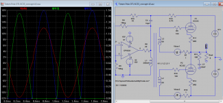
Are you for real? Your graph clearly shows the grid reaching +12V on signal peaks.Also, here is the other chart showing clearly there is no positive grid voltage with respect to the cathode.
Last edited:
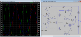
Also the OpAmp output is tied to tube anode via a 1K resistor, somewhat isolated it from global NFB, you can test by change the load resistor from 8 ohms to 80 ohms, the output should be constant.
Any other comments are welcomed.
The inductances shown on your curcuit indicate an impedance ratio of 21:1 and a voltage ratio of 4.6:1.
Ignoring the op-amp for the moment, you have a postive feadback loop with 1 K in series with the reflected and scaled grid resistors - 5 K. So 80% of the output appears across the transformer primary. That equates to oscillation.
All is well perhaps until a large transient or bass thump appears. Then the op-amp is taken outside its linear region, as the fed back voltage will exceed the op-amp supply rails, whereupon its normal very low output impedance will become a very high impedance, allowing the positive feedback loop to become effective.
What will actually happen is a bit diffiucult to visualise, because this is an output stage that will draw lots of grid current, lowering the impedance looking into the transformer primary.
But whether it oscillates or not (and it most likely will) it certainly will sound dreadfull. Bad enough as the OP has it, but by adding C4, you've made it terrible.
Okay.. let me try again.
200mA is pretty low as opposed to the 50-100mA bias current in 60W Class AB transistor amps where peak current is 3.8A?
Sure the grid voltages is reaching 10-12V but cathode voltage is still higher at around 15-17V. So.. Vgk = 15-10 = -5V.. Still negative and not yet grid current teritory.
It's no good going on about the idle current being set to 200 mA. The facts are:-
1. 200 mA is pretty drain low compared with the expected signal peak of 2.5 A;
200mA is pretty low as opposed to the 50-100mA bias current in 60W Class AB transistor amps where peak current is 3.8A?
Two tubes contributing, so it is class AB right? Also, it is not 1W.. It is actually lower as i mentioned earlier: (200mA^2) * 8 / 2 = 160mW.. if i keep the output power below this, it runs in class A. Anything over that, it's class AB.At low signal levels, you have two tubes contributing. At peaks over about 1 watt, you have only one tube contributing.
Are you mixing up which one is grid and cathode voltage? Check again, cathode voltage is green and grid voltage is Blue. Also don't forget that all voltages are with respect to Ground.Are you for real? Your graph clearly shows the grid reaching +12V on signal peaks.
Sure the grid voltages is reaching 10-12V but cathode voltage is still higher at around 15-17V. So.. Vgk = 15-10 = -5V.. Still negative and not yet grid current teritory.
An externally hosted image should be here but it was not working when we last tested it.
What is the class A output power and the total class AB output power?
As mentioned earlier, the output triodes are biased at 200mA. This means if we keep the current flowing to the load (speaker) less than 200mA, the amp stays in class A. 200mA to 8R load equals 160mW.
Even if i increase the output to a miniscule 200mW, it would then run into class AB. The total Class AB output power is around 16-25W, depending on the peak current provided by the 6C33C at Vgk = 0V.
If you would like a true class A 16W amplifier, you need to increase the bias to 2 Amps in which case both triodes are conducting for the whole 16W of output signal.. but sadly Vak=150V and Ic = 2A means 300W of standing dissipation. That 6C33C would surely melt.
Another case is the class AB 60W transistor amp with 100mA of bias current. For the miniscule 40mW of output power, that amp stays in Class A. Anything more than that, it is class AB up to 60W where the peak current is 3.8Amps.
Okay.. let me try again.
200mA is pretty low as opposed to the 50-100mA bias current in 60W Class AB transistor amps where peak current is 3.8A?
Give it up, Ballpencil. What happens in transistor amps isn't relavent.
Transistors don't draw "grid" (base) current over a certain drive level. Base current is required at all times that there is collector current. The terms Class A and Class B are applied to solid state, but the analogy is not very good.
In a tube amp discussion, you need to use the vacuum tube definitions. The definitions are shown on Page 572 of the RDH and they don't even mention the idle current.
Well if the point at which the amp moves out of both tubes conducting, is lower, then the amplifier is even more definitely Class B isn't it!Two tubes contributing, so it is class AB right? Also, it is not 1W.. It is actually lower as i mentioned earlier: (200mA^2) * 8 / 2 = 160mW.. if i keep the output power below this, it runs in class A. Anything over that, it's class AB.
In the region where both tubes are conducting, an approx calculation is this: As one tube goes down 200 mA, the other goes up 200 mA. So the peak output to the load is 400 mA. Power depends on the RMS value however. So the load power is (0.4 x 0.7)^2 x 8 ie 0.63W.
I'm advising you for the third time: You need to put SPICE simulations aside and learn how to read circuits and how to do simple algebraic calculations. You''l be heaps better off if you do. SPICE is for folk who are experienced.
One would have expected the grid drive graph to be with respect to cathode - that is the common convention.Also don't forget that all voltages are with respect to Ground.
Sure the grid voltages is reaching 10-12V but cathode voltage is still higher at around 15-17V. So.. Vgk = 15-10 = -5V.. Still negative and not yet grid current teritory.
If referenced to earth, it cannot be the bottom tube drive as its cathode and grid are offset 150 V negative by the negative supply.
It cannot be the top tube drive, as on +Ve peaks you have it putting out 2.5 A. 2.5 A into 8 ohms equates to a cathode voltage 20 V. 6C33C curves only go to 1A but by extrapolation to get 2.5 A anode current at Va 130V, the grid must be positive (by about 12 to 14V).
In short, it doesn't stack up. You have misread your simulation, and possibly your simulation isn't right anyway. The effects of grid current is something that can trick SPICE implementations, many of which work internally in two steps: 1) calculate no signal conditions, then 2) assume those static conditions hold while calculating signal effects. How accurate is your tube model anyway?
It should be immediately obvious that as you have a standing bias of 47 V and a signal excursion of 122V (+,-61V from the mean each peak), that's more than twice 47 V so the grids MUST go positive. You don't need SPICE to see that, you just need common sense.
Last edited:

The point is, his circuit makes the tubes draw grid current.
Grid current + grid capacitors = lots of distortion.
Grid current + grid capacitors = lots of distortion.
Another case is the class AB 60W transistor amp with 100mA of bias current. For the miniscule 40mW of output power, that amp stays in Class A. Anything more than that, it is class AB up to 60W where the peak current is 3.8Amps.
That transistor amp is a Class B amp. Calling typical solid state amps AB is a common misconception. They are Class B because each output transistor is cut off for approximately half a cycle. That is precisely the definition of Class B. And it makes cross over distortion an issue that the design engineer MUST address.
I thought it was a clear cut case.
It is. It's an AB1 circuit. Operating angle is not 180 degrees. It's also not 181 degrees. 😀
NB: I am not saying your sim is right or wrong, nor if your circuit is good or bad. It's not the way I would design an OTL, but in my father's house, there are many mansions.
There has to be some overlaps because the conduction angle depends to some extends on grid bias, as well as precise driver voltage level and angle. If bias current current is to little and driver voltage get more precise such as in this case of inter-stage trans couple, you can get cross over distortion more easily than a driver using cap and resistor coupling. Usually the conduction is seldom 180 degree apart (perfect Class B) one way or the other. Cross over distortion in class AB can be corrected due to overlap, but still appear at high output and clipping due to reduce gain for NFB to operate. It appears that cross over distortion in Class B can not be corrected, even at low output level, that why Class AB is "invented".
I read the story of perfect Class B design before any one can point it out where it can be located?
I read the story of perfect Class B design before any one can point it out where it can be located?
Attachments
Last edited:
Sy,
It's clearly Class B. Read the definition I quoted straight out of the Radiotron Designers' Handbook.
An AB output stage is one whether the tubes are each cutoff for much less than half a cycle. Class B is where each tube is cut off for approximately half a cycle.
There is no point in splitting hairs over whether its 180 or 181 or 190 or 170 degrees. The practicalities of tube design mean that an amplifier that cuts its tubes off for appoximately half a cycle, with very few exceptions, must draw grid current (or the power output will be less than with the same tubes in Class A - negating the only reason for using Class B).
But actually, whether it is Ab or B or X or YZ, isn't the main point. The main point is the OP's circuit causes the tubes to go well into grid current.
Grid current + grid capacitor means lots of distortion due to overbias. And post large signal parallysis as until the grid caps discharge back toward static conditions the tubes are held cut-off and ignore or heavily distort any small amplitude signals.
Last edited:
It's clearly Class B. Read the definition I quoted straight out of the Radiotron Designers' Handbook.
I did.
There has to be some overlaps because the conduction angle depends to some extends on grid bias, as well as precise driver voltage level and angle. If bias current current is to little and driver voltage get more precise such as in this case of inter-stage trans couple, you can get cross over distortion more easily than a driver using cap and resistor coupling. Usually the conduction is seldom 180 degree apart (perfect Class B) one way or the other. Cross over distortion in class AB can be corrected due to overlap, but still appear at high output and clipping due to reduce gain for NFB to operate. It appears that cross over distortion in Class B can not be corrected, even at low output level, that why Class AB is "invented".
I read the story of perfect Class B design before any one can point it out where it can be located?
Cross-over distortion that occurs well up in the transfer curve is a lot more benign than cross-over distortion at or near the zero crossing, because the statistical nature of music means that the zero crossing is traversed much more often than points well up on the transfer curve.
This is why certain solid sate amps that are designed with a quite heavy standing current (0.5 amp for example, or more) aren't any better on a THD test (and may be worse) but DO sound very good. The cross-over distortion from gain change is still there, just as bad, but its moved to a part of the transfer curve where it doesn't matter so much.
This was very well demonstrated by the Hitachi Class H solid state amps they sold in the 1970's. This topology has multiple output transistors interpolating between multiple supply rails. Eg one transsitor has control of the speaker current betwen +100V and +60V, another between +60V and 0V, another between 0V and -60V and yet another between -60 and -100V. They were carefull about the 0V crossover but were quite sloppy about the crossovers at +60V and -60V. You could see them easily on a CRO. But quite inaudible.
Some Class D amplifiers (switchmode) display artifacts that look just like cross-over distortion on a CRO, at various non-zero places on the output range. They arise because switching harmonics come and go with instantaneous signal level. Due to lead lengths and board layount certain harmonics get into the input and corrupt the pulse width modulation and some don't. These artifacts make a THD test look bad, but are generally inaudible on music. They often are audible on a sine wave test.
Last edited:
I did.
Just in case you and BallPencil need a bit of reinforcement on understanding tube amplifier classification.....
Following are definition I've copied out directly from Theory and Applications of Electron Tubes, 2nd ed by Herbet J Reich, McGraw-Hill, page 139. Another well regarded standard work.
"According to the portion of the cycle during which plate current flows, amplifiers are classified as Class A, Class Ab, Class B, and Class C.
"A Class A amplifier is one in which the the grid bias and alternating grid voltage are such that plate current in the tube(s) flows at all times.
"A Class AB amplifier is one in which the the grid bias and alternating grid voltage are such that plate current in the tube(s) flows for appreciably more than half but less than the entire electrical cycle.
"A Class B amplifier is an amplifier in which the grid bias is approximately equal to the cut-off value, so that plate current in each tube flows for approximately one-half of each cycle when an alternating grid voltage is applied.
Notice the words appreciably and approximately used in the definitions of Class AB and B. These words are important. They make the definitions useful in practice.
Notice that these definitions, while not identical to the Radiotron Handbook definitions, they are essentailly the same. They hinge on the conduction angle.
It matters not a whit how the bias is obtained, fixed bias applied to the grid, or developed by grid rectification charging a grid coupling capacitor, any given amp fits into these definitions just the same.
BallPencil's amp is clearly Class B according to both Reich and Radiotron. It's unimportant from a classification point of view that the standing bias allows some tube current to flow. Additional bias is developed by grid current to make it Class B.
If you think it can be called AB or aB because both tubes conduct under small signals, then by the same reasoning you should be calling it aBC, because under certain conditions (following a heavy music passge or large transient) the thing operates with each tube cut off for appreciably more than half a cycle - that's the definition of Class C. Class C of course normally confined to radio transmitters where linearity is unimportant.
Last edited:
Sy,
But actually, whether it is Ab or B or X or YZ, isn't the main point. The main point is the OP's circuit causes the tubes to go well into grid current.
It doesn't look like that, based on the SPICE simulations. The grid voltage seems to be always negative relative to the cathode.
The 6C33C doesn't need positive grid voltage (relative to cathode) to get the anode current up to 2.5A.
Chris
Well--Who Cares, A, AB, B, C These are just letters so who really cares....!
What should be more important--is addressing the distortion that occurs when grid-current is drawn.
Suggest a MOSFET Grid Driver for the output pair, or redesign to remove the coupling-caps and use the transformer secondaries direct....
What should be more important--is addressing the distortion that occurs when grid-current is drawn.
Suggest a MOSFET Grid Driver for the output pair, or redesign to remove the coupling-caps and use the transformer secondaries direct....
- Status
- Not open for further replies.
- Home
- Amplifiers
- Tubes / Valves
- Another Approach to Totem Pole OTL Amplifier