The cone holes are not filled in in any of the dual driver DSL designs.
That's because you're still thinking of the issue in terms of your definition of cone correction, which requires that, and not mine. But, before I go further on this, a quick question for you - do you believe that HornResp can be used to sim a TH that uses two drivers in close proximity placed in tandem?
That's because you're still thinking of the issue in terms of your definition of cone correction, which requires that, and not mine.
With all due respect, I think neither you or I or anyone else should have a personal definition of "cone correction" that differs from the concept that's been discussed in depth and already has a definition. It's been defined by the guy that invented it, and at least a couple hundred subsequent posts have all looked at it by the same definition. To describe it quite simply, it's filling in the cone hole.
I'm not sure why you even want to call DSL's "stub" "cone correction" anyway. Why not just call it a "stub" like DSL does?
But, before I go further on this, a quick question for you - do you believe that HornResp can be used to sim a TH that uses two drivers in close proximity placed in tandem?
Yes, but not completely accurately. Back since MJK's early days the convention has been to consider them as one when using software that can only account for a single driver, and it's kind of good enough but as people that have simulated them separately have noted, it's not as accurate as simulating them individually.
I have a pretty good idea where you are going with this, wavelengths again. But I can only repeat what I've said before - you can't fill in a hole by placing fill beside the hole, so "cone correction" does not apply here. Furthermore, you can't relieve unsymmetrical pressure by placing a restriction between cones. I believe Ricci has already studied this, simulated in Akabak, and stated that the load on the two drivers is NOT the same. I'd go a step further and say that the unsymmetrical load on each individual driver is not alleviated by the "stub" even though I haven't simulated it and this is just speculation. So none of the requirements of "cone correction" definition are realized with a "stub".
I do believe that you've identified a few other good reasons for the "stub". Longer path length, altered frequency response, allowing the driver near the throat to be flipped and still preserve decent csa in that narrow throat area in dual driver designs. These are all good and valid reasons to use a "stub" and there's probably more too. But a "stub" doesn't fill in the cone hole, so by definition it's not "cone correction".
With all due respect, I think neither you or I or anyone else should have a personal definition of "cone correction" that differs from the concept that's been discussed in depth and already has a definition. It's been defined by the guy that invented it, and at least a couple hundred subsequent posts have all looked at it by the same definition. To describe it quite simply, it's filling in the cone hole.
As I've mentioned before, let's stick to MY definition for this thread, which is simply to ensure the TH's layout takes into consideration the volume of air contained within the driver's cone. I'm not interested in other definitions.
I'm not sure why you even want to call DSL's "stub" "cone correction" anyway.
As I have not referred to DSL's stub as "cone correction", I'm really not sure what you're on about. I have mentioned several times in the past that the appears to be a lot more than "cone correction" going on in his designs, and even included a worked example showing how further restriction at S2 that goes above and beyond cone correction, which is what appears to be happening in some of the DSL designs, can produce some benefits.
Yes, but not completely accurately.
The sim does not have to be completely accurate. NO sim I know about is "completely accurate", BTW - they all have varying degrees of accuracy. However, an experienced designer/engineer would know when a particular sim is accurate enough for design purposes, and not worry about various other details in the build that are not referenced in the sim, as they would make very little difference if they were. You know, things like grilles...
In the case of bass horn design, the wavelengths concerned are many times longer than the dimensions involved here, so I can say that the HornResp sim of a dual-driver tandem design can be "accurate" enough" for designing them.
But I can only repeat what I've said before - you can't fill in a hole by placing fill beside the hole, so "cone correction" does not apply here. Furthermore, you can't relieve unsymmetrical pressure by placing a restriction between cones. I believe Ricci has already studied this, simulated in Akabak, and stated that the load on the two drivers is NOT the same.
Why are you still sticking to some other definition of cone compensation that I've already said that I'm not interested in discussing here? My definition says nothing about "filling in holes".
If you want me to state the purpose of my approach to cone compensation, it is simply to make the correlation between the built TH and the HornResp sim more accurate - refer to my very first post that started this thread. As for the other supposed advantages, it would be nice if they happen, but that's not my focus here. I initially started thinking about it in terms of CSA changes at S2, but soon discovered that it's more correct to think about the issue in terms of VOLUME changes at S2, and this applies to both single and tandem designs. This can be clearly demonstrated in HornResp, and if you believe that HornResp is accurate enough to sim a tandem driver TH, it can be demonstrated for those as well.
The very nature of the TH simulation in Hornresp and Akabak is imperfect from the point of view that the driver is just a point of energy there is no distribution by SD, it is purely a mathematical construct that cannot exist in our physical world.
Last edited:
How so? A real world flat piston's acoustical performance is used to sim drivers, vents, etc..
GM
GM
The mathematical model does not distribute the energy driving the horn by SD, it is literally a site of injection for the calculation. Even the flat piston construct has an area that the math does not consider.
As I've mentioned before, let's stick to MY definition for this thread, which is simply to ensure the TH's layout takes into consideration the volume of air contained within the driver's cone. I'm not interested in other definitions.
Well, this has been beat to death. Call it what you want, even if your definition is a complete redefinition of a known concept.
As I have not referred to DSL's stub as "cone correction", I'm really not sure what you're on about. I have mentioned several times in the past that the appears to be a lot more than "cone correction" going on in his designs, and even included a worked example showing how further restriction at S2 that goes above and beyond cone correction, which is what appears to be happening in some of the DSL designs, can produce some benefits.
Don't remember what started all this? Here it is, check the bold parts.
Mr. Steele,
Here is a comment about tapped horn design by Ian Beaver, an engineer at Danley, that I have never seen anyone post on diyAudio. I think the cone compensation might be the "magic" element he is referring to, as that is the only real difference I see between the majority of subs designed here, and actual Danley tapped horns.
DIY SUBs design suggestion
Ian Beaver: "Obviously I can't speak for all of them, but most (if not close to all) of the DIY designs for a Tapped Horn are not getting one crucial part of the design correct. In many cases "simple theory" gets you in trouble.
There have been a number of Toms designs that did not perform as we wanted-so they are not available. We have pretty much narrowed down what it takes, and we are not telling anybody.
The way Tom designs a Tapped horn is he uses a couple of different prediction programs-rolls it around in his head-mixed with lots of EXPERIENCE of all sorts of tapped horns and comes up with a design.
It is NOT a simple "enter the numbers into the computer and get a result" that most people use."
It may be, but I have a suspicion that he may have found out inserting a "pinch" in the horn at S2 may also produce beneficial results, similar to what I discovered with my "dog food duct", which inserts a pinch between S2 and S3 which can eliminate the first major notch in the FR of a single-expansion TH.
I aim to test something similar in my next "test case". HornResp cannot sim the effect of a pinch at S2 however (unless David modifies it to allow negative Vtc, LOL), so I'll basically be "flying blind" with that test.
I'm not going to search through all this to find out how many times you've called DSL's stub "cone correction", but I've been arguing that it's not since like page 2 and you've been arguing with me about the definition of "cone correction" to include DSL's "stubs".
The sim does not have to be completely accurate. NO sim I know about is "completely accurate", BTW - they all have varying degrees of accuracy. However, an experienced designer/engineer would know when a particular sim is accurate enough for design purposes, and not worry about various other details in the build that are not referenced in the sim, as they would make very little difference if they were. You know, things like grilles...
In the case of bass horn design, the wavelengths concerned are many times longer than the dimensions involved here, so I can say that the HornResp sim of a dual-driver tandem design can be "accurate" enough" for designing them.
Not all sims have to be completely accurate. But in this VERY SPECIFIC case where you were trying to account for a couple hz difference between a sim and a measurement, accuracy is EVERYTHING.
And grills do matter.
But leave the grill out of the sim and take it out for the measurement and the grill doesn't matter anymore. That's probably about as close as we are going to get on a consensus on this issue.
Why are you still sticking to some other definition of cone compensation that I've already said that I'm not interested in discussing here? My definition says nothing about "filling in holes".
If you want me to state the purpose of my approach to cone compensation, it is simply to make the correlation between the built TH and the HornResp sim more accurate - refer to my very first post that started this thread. As for the other supposed advantages, it would be nice if they happen, but that's not my focus here. I initially started thinking about it in terms of CSA changes at S2, but soon discovered that it's more correct to think about the issue in terms of VOLUME changes at S2, and this applies to both single and tandem designs. This can be clearly demonstrated in HornResp, and if you believe that HornResp is accurate enough to sim a tandem driver TH, it can be demonstrated for those as well.
You've made it quite clear that you don't care about the well known definition of this well known concept.
Making the sim match the measurement is NOT "cone correction", it's just the process of accuracy in simulation.
You've completely redefined the process AND the purpose but kept the name. It's weird, but whatever. Do what you like.
I'm not going to search through all this to find out how many times you've called DSL's stub "cone correction", but I've been arguing that it's not since like page 2 and you've been arguing with me about the definition of "cone correction" to include DSL's "stubs".
No, I've not. BTW, see that section you quoted? it's DHAA that suggested that "cone correction" might be the "magic element", not me. You even QUOTED where he suggested this, and still you're suggesting that it was ME who suggested it was cone correction? Really? LOL.
And grills do matter.
Keep beating that dead horse, LOL. One day it might wake up 😉
Yeah, the next quote was you saying "It might be", talking about "cone correction" being DSL's secret ingredient. Did you completely miss the quote after DHAA's? It was your comment. LOL all you want.
You are free to prove grills don't make any difference if you like, but I'm pretty sure you would have already if you could.
At this point I've made my points really clearly, I think, there's no point in repeating further. I clearly do not agree with you and that's not going to change but since the tone is slightly more civil now I'll leave you alone to say what you like.
Yeah, the next quote was you saying "It might be", talking about "cone correction" being DSL's secret ingredient. Did you completely miss the quote after DHAA's? It was your comment. LOL all you want.
Then I went on to say, and I quote: "but I have a suspicion that he may have found out inserting a "pinch" in the horn at S2 may also produce beneficial results..."
Last time I checked "might be" is not the same as "is". And I clearly indicated that I believed that an S2 pinch might actually be the secret ingredient. You actually quoted my complete statement in my last post, but left out that part in your last post, I wonder why? I really wish you'd stop quoting me out of context like that.
You are free to prove grills don't make any difference if you like, but I'm pretty sure you would have already if you could.
I don't have to - I already know that they don't make any difference, at least any difference significant enough that I have to worry about it.
At this point I've made my points really clearly, I think, there's no point in repeating further.
Thanks. Repeating the same things over and over in Goebbels-style fashion does not make them any more valid.
So, here's a little mental exercise to try with your example:
1. Flip the bottom driver and adjust the volume between S1 and S2 to compensate.
2. Increase S2 to negate any pinch that may have been implemented there for cone correction.
What do you end up with?
I see you didn't bother to try out my exercise, so let me give a worked example.
The 1st image is a HornResp model of a two-driver TH, including its schematic and its frequency response. What's missing from the sim? There's no figure for Vtc, so the impact of the volume of air contained in the cones is not being taken into consideration.
Now, let's consider that this is two 15" drivers facing into the baffle. That adds up to about 9L of volume at Vtc that's not being taken into consideration. If we adjust the model to include this, we end up with what's shown in the 2nd image.
Now, we want to implement "cone compensation", i.e. to adjust the TH's layout to bring it back to the response shown in the first image. How can we do this? Well, the results of the HornResp model suggests we can do that by simply pinching in S2 a bit, bringing the TOTAL volume in the schematic back to 348 L. Check the FR of the sim in the 3rd diagram. It is basically identical to the one in the first figure. The conclusion is an obvious one - if you agree with me that HornResp is good enough for modelling a tandem-driver TH, then it's clear from the sim that pinching CSA at S2 (rather than adding pinches in front of each driver) can be used for "cone compensation".
Now, finally, let's consider the case of where one of the drivers is reversed, so its basket actually sits in S1. See the 4th diagram. For 15" drivers, the volume this is likely to displace can about 7.5L. So we need to ADD 7.5L to the horn at that location to ensure that the FR remains the same as shown in the model. How do we do this? Well, if it's the driver closest to S1 that we're switching, we can simply increase S1 until the model's TOTAL volume reflected in the model goes up by 7.5L. In this case, S1 needs to be increased from 500 cm^2 to 875 cm^2. REMEMBER, if we want to see what the FR is going to look like, we will have to decrease S1 back to 500 cm^2 in the model, as HornResp does not provide a means of actually modelling the effect of a driver's basket in the S1-S2 section - we're just using HornResp here to help figure out how much we have to increase S1 in the build to compensate for it.
Is that schematic beginning to look familiar to anyone?
Now, let's try a "pinch" at S2 to see what happens. See the 5th image. Basically I've (1) returned S1 to 500 cm^2 for modelling purposes, (2) reduced S2 to give a somewhat better response around the notch, and finally (3) increased S1 to what it would have to be IN THE BUILD to reflect the additional 7.5L that's required between S1 and S2 to compensate for the driver's basket, and bring the results more in line with the model.
Attachments
Even the flat piston construct has an area that the math does not consider.
???
Try changing the value of Sd in any Hornresp simulation 🙂.
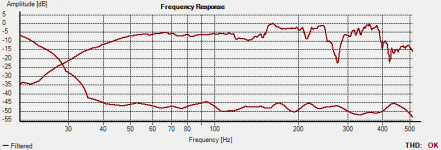
I decided to take the frequency response of my POC#3 with "cone compensation" and no DSP filtering to see what the raw response looks like. The results are as expected - the two "notches" in the FR, one around 129 Hz and the other around 280 Hz have filled up a bit, compared to the response without cone compensation. Another thing that's noticeable is that the "out of band noise" between 150 Hz and 200 Hz seems to be less peaky in nature.
In fact, the results are encouraging enough that I'm tempted to try pinching S2 even further, quite a bit beyond that predicted as required for cone compensation. Now I just have to figure out the best way to do it...
Note - this is a close-miked FR, done at a different level to the previous FR measurements given in this thread. The distortion levels therefore won't be comparable.
Attachments
???
Try changing the value of Sd in any Hornresp simulation 🙂.
Hi David,
Have I overlooked something WRT how the driver energy is interfaced to the model?
Have I overlooked something WRT how the driver energy is interfaced to the model?
Hi Dan,
Not really, it's more a question of clarification / qualification 🙂.
I had no problems with the first sentence:
The mathematical model does not distribute the energy driving the horn by SD, it is literally a site of injection for the calculation.
With regard to the second sentence, I know what you are getting at in terms of the driver being treated as a point source, but I thought that it had the potential to confuse people, in that Sd is obviously a factor in determining the amount of sound energy actually produced by that point source.
Even the flat piston construct has an area that the math does not consider.
From his comment, I suspect that GM also had some concerns with the second statement 🙂.
Kind regards,
David
I decided to take the frequency response of my POC#3 with "cone compensation" and no DSP filtering to see what the raw response looks like. The results are as expected - the two "notches" in the FR, one around 129 Hz and the other around 280 Hz have filled up a bit, compared to the response without cone compensation. Another thing that's noticeable is that the "out of band noise" between 150 Hz and 200 Hz seems to be less peaky in nature.
In fact, the results are encouraging enough that I'm tempted to try pinching S2 even further, quite a bit beyond that predicted as required for cone compensation. Now I just have to figure out the best way to do it...
Note - this is a close-miked FR, done at a different level to the previous FR measurements given in this thread. The distortion levels therefore won't be comparable.
Brian, these are the results I would naturally expect to happen from merely increasing compression ratio (fills the dips, causes compression to knock down the high pressure peaks).
No probs 🙂
I took the original HornResp parameters you provided, corrected them (by changing the expansion to Par and adding in a value in Vtc that's an approximate value for the volume of air sitting in front of the cone and in the driver cutout). I then converted the model to an S1-S5 version, and then pinched the CSA at S2 in that model down to 121 cm^2. The results look promising - see attached image.
This goes beyond "cone compensation" though, which IMO is just ensuring that the TH layout takes into consideration the volume of air contained in front of the driver's cone. We're actually significantly pinching in the CSA at S2 - see second image - quite a bit more than what would be required for cone compensation. The change in layout will look similar, but it's not the same.
I do not belive that the pinching is an accurate way to go..
If you look at Xoc1's drawing of the cone you see that it's almost U-shaped.
When you insert a pinch you get a V-shape instead in the throat, that pinch will not distribute the pressure equally over the cone.. It will also create a low pressure zone at S1...
I Think the best way to compensate for the cone is to make a model similar to the cone and put in front. If you do so, then you don't have to take the cone volume into account in the simulation..
As just a guy said, accurate simulations gets accurate measurements..
I do not belive that the pinching is an accurate way to go..
You've got to consider the wavelengths of the frequencies in question here. Remember this is a bass speaker, not a full-range speaker 🙂.
Anyway, proof of the pudding is in the eating - see The Subwoofer DIY Page v1.1 - Projects : "Proof of Concept #4"
Yes, i understand what the aim is, but you are not taking into account the pressure against the cone.. a pressure does not have any wavelengths.. i don't say that your concept does not work, i think it is in fact a smart and easy way to make the build more accuerate. What i meen is that if you really want to compensate the cone you need to have something that also evens the pressure adequate.. lets face it, we are dealing with quite high compression ratios in modern TH. 2,5-3:1 is not that unusuall..
Skickat från min SM-T310 via Tapatalk
Skickat från min SM-T310 via Tapatalk
Yes, i understand what the aim is, but you are not taking into account the pressure against the cone.. a pressure does not have any wavelengths..
Sound is a Pressure Wave
- Status
- Not open for further replies.
- Home
- Loudspeakers
- Subwoofers
- "cone compensation" - a test case