thank you indeed but i already have these docs.The theory is in the first few pages
Filler drivers
John K's website with spreadsheet:
http://www.reocities.com/kreskovs/GenFiller.html
The B&O patent:
Patent US4031321 - Loudspeaker systems - Google Patents
and the later links in this post
http://www.diyaudio.com/forums/multi-way/88135-filler-driver-ala-b-o-7.html#post4381538
no other material about it ?
to few sources, why ?
diypass,
There is chance it would be mentioned somewhere on John Kreskovsky official site Music and Design there is tons of good speaker knowledge both for his builds and at the "Tech Studies" link.
At this http://www.diyaudio.com/forums/multi-way/174276-wmtmw-baekgaard-2.html#post2315946 thread post 16 you can find info to buy pro papers from AES library at fair cost.
As a diy i don't get why you say few sources, get the spreadsheet from John Kreskovsky make the targets that suit your intended build, then export target curves as frd files and import them in your other software tools or measurement tool and get drivers to perform those curves acoustic : )
There is plenty of reading with above links. I have not had a chance to read them carefully yet. I figured it would be OJT if I just built it and tried to get it to work. Maybe not the best strategy but certainly more fun than going through complex variable algebra of transfer functions 1/(s+1) etc. 🙂
Given that it is based on complex variable algebra of transfer functions and the requirement is that they add up to unity in a phase coherent way - there are infinite solutions limited only by your time. For a 3 way, the simplest and most practical solution (given typical driver bandwidths and need to limit cone excursion), the LR2 is probably best lowest order filter for the woofer and tweeter. The mid filler driver has to be 1st order or maybe 3rd order in order to be same phase. Butterworth first seems reasonable to effect some cone control for a wide band driver with xo freq well above fs to avoid over excursion.
So I think reality is that LR2-BW1-LR2 is the simplest and most practical. With FIR filters and rephase and DRC, you can run almost any Order filter and it will work.
X,
Given lively nature of your space, reflections are highly problematic in capturing direct sound. This causes difficulty in using sine wave and scope view for delay alignment; and leads to gut wrenching views when capturing square waves. Windowing IR and convolving with square wave will give clearer view of speaker behavior.
Your woofer contributions at 1kHz range are quite large; as well their relative distances from mids and tweeter. Large format speaker with low order crossover comes into focus effectively in far field (several meters); at which point room reflections swamp direct sound.
Use of swept square wave, readily produced with Audacity, help tell the tale. With your reference monitor using BW1 crossover you can watch square wave performance at various distances and see the impact of room reflections on waveform envelope.
Linkwitz was amazed when he built Pluto and found that aside from deep base and SPL capabilities it's similarity to his Orion; imaging of Pluto is better. This pushed his baffle design for his LX in direction that many DIY players were already exploring. WMTMW is easier to focus over broader range of distances with low order filters. Line array such as wesayso's blows WMTMW away. Once in large format land one might as well go for it.
Some humor. Here is waveform of cello playing G on D string with bow and other strings not damped:

Waveform is not unlike square wave with 25% duty cycle. Recording played through most speakers sounds like cello recording played through a speaker. When played through coherent speaker it sounds like cello.
Recording was made by me in living room with microphone at about 1 meter.
Given lively nature of your space, reflections are highly problematic in capturing direct sound. This causes difficulty in using sine wave and scope view for delay alignment; and leads to gut wrenching views when capturing square waves. Windowing IR and convolving with square wave will give clearer view of speaker behavior.
Your woofer contributions at 1kHz range are quite large; as well their relative distances from mids and tweeter. Large format speaker with low order crossover comes into focus effectively in far field (several meters); at which point room reflections swamp direct sound.
Use of swept square wave, readily produced with Audacity, help tell the tale. With your reference monitor using BW1 crossover you can watch square wave performance at various distances and see the impact of room reflections on waveform envelope.
Linkwitz was amazed when he built Pluto and found that aside from deep base and SPL capabilities it's similarity to his Orion; imaging of Pluto is better. This pushed his baffle design for his LX in direction that many DIY players were already exploring. WMTMW is easier to focus over broader range of distances with low order filters. Line array such as wesayso's blows WMTMW away. Once in large format land one might as well go for it.
Some humor. Here is waveform of cello playing G on D string with bow and other strings not damped:
Waveform is not unlike square wave with 25% duty cycle. Recording played through most speakers sounds like cello recording played through a speaker. When played through coherent speaker it sounds like cello.
Recording was made by me in living room with microphone at about 1 meter.
I had a look at the transfer functions needed for a filler driver topology that uses a 4th order bandpass and high- and lowpass functions with 3rd order final rolloff.
The humps and the overlap would be too large - at least for the case where all the pole frequencies are the same and all Q values are 0.5.
But I will have a look at what happens when the pole frequencies are split and the Q is different from 0.5.
Regards
Charles
The humps and the overlap would be too large - at least for the case where all the pole frequencies are the same and all Q values are 0.5.
But I will have a look at what happens when the pole frequencies are split and the Q is different from 0.5.
Regards
Charles
Last edited:
X,
Given lively nature of your space, reflections are highly problematic in capturing direct sound. This causes difficulty in using sine wave and scope view for delay alignment; and leads to gut wrenching views when capturing square waves. Windowing IR and convolving with square wave will give clearer view of speaker behavior.
Your woofer contributions at 1kHz range are quite large; as well their relative distances from mids and tweeter. Large format speaker with low order crossover comes into focus effectively in far field (several meters); at which point room reflections swamp direct sound.
Use of swept square wave, readily produced with Audacity, help tell the tale. With your reference monitor using BW1 crossover you can watch square wave performance at various distances and see the impact of room reflections on waveform envelope.
Linkwitz was amazed when he built Pluto and found that aside from deep base and SPL capabilities it's similarity to his Orion; imaging of Pluto is better. This pushed his baffle design for his LX in direction that many DIY players were already exploring. WMTMW is easier to focus over broader range of distances with low order filters. Line array such as wesayso's blows WMTMW away. Once in large format land one might as well go for it.
Some humor. Here is waveform of cello playing G on D string with bow and other strings not damped:
View attachment 492599
Waveform is not unlike square wave with 25% duty cycle. Recording played through most speakers sounds like cello recording played through a speaker. When played through coherent speaker it sounds like cello.
Recording was made by me in living room with microphone at about 1 meter.
As usual, your observations are spot on and I am guessing that I won't be able to capture a square wave unless I take this outside. That is a lot of work and it is hot and humid now so not pleasant. I think looking at the derived step response, I am confident that the square wave would at least resemble the first 1.2 ms of the SR. A slight droop in the amplitude with a small dip at the leading edge. Good idea with swept square wave.
My lively room is indeed a problem and perhaps wall damping and sound treatments should be up for major effort one of these days. I know Wesayso added panels to his room and it helped.
I have a large 2 story family room and foyer that is 50ft long and 22ft ceiling x 25ft wide. I wonder if that is close enough to "open" space that a measurement would be improved?
That would be indoors and air conditioned with less noise from cars, kids, airplanes, birds etc.
Pop up IR.wav of your last two results and I will investigate windowing and square waves with Cool Edit; only takes a couple of minutes. Export from REW with rectangular window:

File will be about 32k; just do the usual and change extension to .asc.
File will be about 32k; just do the usual and change extension to .asc.
With some digging I found that I already did the maths for the fourth order polynome some years ago.
I even prepared an Excel spreadsheet.
If used as pure filler driver concept it is not worth the hassle. The humps are about 3dB in height which does not weigh up the increased steepness of the filters IMO - especially when their only gradual rolloff is taken into account.
Regards
Charles
I even prepared an Excel spreadsheet.
If used as pure filler driver concept it is not worth the hassle. The humps are about 3dB in height which does not weigh up the increased steepness of the filters IMO - especially when their only gradual rolloff is taken into account.
Regards
Charles
Attachments

With some digging I found that I already did the maths for the fourth order polynome some years ago.
I even prepared an Excel spreadsheet.
If used as pure filler driver concept it is not worth the hassle. The humps are about 3dB in height which does not weigh up the increased steepness of the filters IMO - especially when their only gradual rolloff is taken into account.
Regards
Charles
Thanks for looking into this. So is the LR2-BW1-LR2 the simplest way to get a response that sums flat and has decent cone control for woofer and tweeter?
Hi xrk971,
Attached are my simulations using idealized drivers mounted on an infinite baffle, plus a sim with each driver having a limited bandwidth of 2 decades in frequency and including appropriate acoustic offsets.
Hopefully, there is enough data defined in the block diagram for you to understand the basis of the simulations, but feel free to ask for more info if anything is unclear.
Hope this is of some help.
Peter
Attachments
xrk971
So is the LR2-BW1-LR2 the simplest way to get a response that sums flat and has decent cone control for woofer and tweeter?
Decent control yes, but if you/someone could use suitable drivers that could take advantage of BW1-BW1-BW1 all in phase, as i demo'ed, & time aligned, that would be even better, in Lots of ways 😉
Ok, so the 10F is a tweeter with super wide bandwidth, and the 5FE120 is a mid
I've never tried that but I think it could be a good idea. Not from vertical lobing POV, but I found that the filler driver quality (apart from being able to reproduce wide bandwidth) is not critical.
I have owned a similar design for almost 5 years (tho rarely used) and few days ago I tried prototyping another one with better filler driver. What I found was that I have sacrificed/wasted the mid-driver "potential" by using it as filler driver. This could happen if 10F is used as a filler driver.
Hmm... I like the XT25 too
Many good designers have praised the tweeter. Often with extra words: "when done right". It IS that "special". However, it has rolled-off off-axis HF performance, but if you can accept full-range driver's treble, there will be no issue in that regard.
Apart from having low Fs, it is not really suitable to be crossed low. The non-linear distortion is "premium" at 3kHz and above. I couldn't accept LR4 at 2k4, even with notch filter. LR4 (with notch filter) at 2k5 is the minimum I could accept, with performance slightly less than tweeters many times the price. But I have never found the tweeter to sound "special" when main resonance notch filter is not used (even if crossed high).
The tweeter has a "strange" waveguide that affect frequency around 2k7, so this frequency can be treated as another reference point, i.e. you can cross above 2k7 if you need to (unless you modify the waveguide).
if you/someone could use suitable drivers that could take advantage of BW1-BW1-BW1 all in phase, as i demo'ed, & time aligned, that would be even better, in Lots of ways 😉
Because talking about electrical slope is often meaningless, I assumed that you are talking about acoustical slope there. Frankly I have never found drivers combination (it's three!) that can do it. May be I have, but couldn't accept the result. It is not just about flat response and phase, but using a driver for such a wide bandwidth requires drivers with low non-linear distortion for a wide bandwidth, which will make the ideal driver unobtainable.
I have owned a similar design for almost 5 years (tho rarely used) and few days ago I tried prototyping another one with better filler driver. What I found was that I have sacrificed/wasted the mid-driver "potential" by using it as filler driver. This could happen if 10F is used as a filler driver.
It seems that a budget PA130-8 may be just the perfect filler driver then. It has wide bandwidth. and is smooth enough where it counts.
Hi xrk971,
Attached are my simulations using idealized drivers mounted on an infinite baffle, plus a sim with each driver having a limited bandwidth of 2 decades in frequency and including appropriate acoustic offsets.
Hopefully, there is enough data defined in the block diagram for you to understand the basis of the simulations, but feel free to ask for more info if anything is unclear.
Hope this is of some help.
Peter
PLB,
Thanks for doing this! I am trying to figure out what you did. There are two systems, the first being LR2-BW1-LR2 at 0.5 overlap, and the second is LR2-LR2-LR2 at 0.71 overlap?
So based on the shape of the response that I have, it looks like it is acoustically, LR2 all around, given the peak on leading edge followed by dip and rise? Is that what your sim is trying to show?
Last edited:
PLB,
Thanks the documentation its nice made.
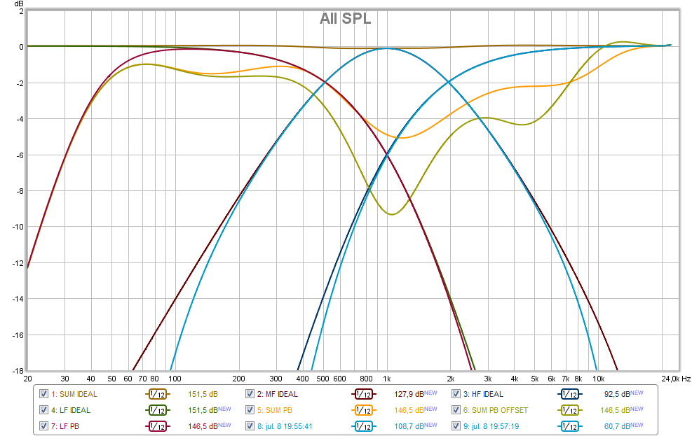
Did copy your setup by looping back a USB soundcard at 16bit/48kHz thru JRiver DSP engine with same filters plus delay setup and listening in loop with REW. Below is REW plot and added the orange which is error still present even drivers are aligned but bandwidth limited.
xrk971,
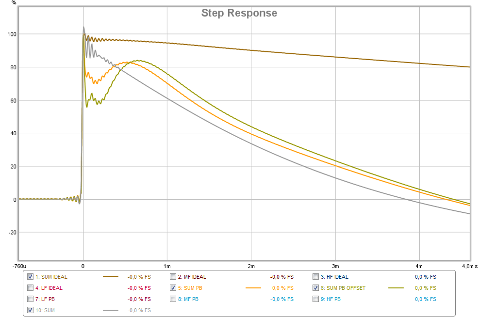
Think PLB try to point out if the electric XO slopes are connected perfect ideal drivers DC-infinite bandwidth system sum are perfect. Then when he use same electric XO slopes at real bandwidth limited bandpass drivers, a 40-4kHz LF, a 100-10kHz MF and a 4kHz-40kHz HF and at same put the acoustic offset error in by a 0,1mS LF delay and a 0,03mS MF delay then system sum is full of errors, and mayby its more the SR error he want to point out looks some ala yours. The below SR plot is a REW copy of that PLB did, brown is perfect system with infinite bandwidth, grey i added and is a 40-22kHz system (X's OB) with no errors for bandwith or offset, orange i also added and is the bandwidth limited drivers, and gold is the bandwidth limited drivers plus their acoustic offset errors.
So it's simple X : )
First get the drivers to perform their slopes acoustic, but important its also done below -20dB and down deep.
Second get acoustic offset callibrated 100%.
Third get their SPL sum calibrated 100%.
Fourth enjoy square waves and music....🙂
Fifth really easyer said that done 🙁
Thanks the documentation its nice made.
Did copy your setup by looping back a USB soundcard at 16bit/48kHz thru JRiver DSP engine with same filters plus delay setup and listening in loop with REW. Below is REW plot and added the orange which is error still present even drivers are aligned but bandwidth limited.
xrk971,
Think PLB try to point out if the electric XO slopes are connected perfect ideal drivers DC-infinite bandwidth system sum are perfect. Then when he use same electric XO slopes at real bandwidth limited bandpass drivers, a 40-4kHz LF, a 100-10kHz MF and a 4kHz-40kHz HF and at same put the acoustic offset error in by a 0,1mS LF delay and a 0,03mS MF delay then system sum is full of errors, and mayby its more the SR error he want to point out looks some ala yours. The below SR plot is a REW copy of that PLB did, brown is perfect system with infinite bandwidth, grey i added and is a 40-22kHz system (X's OB) with no errors for bandwith or offset, orange i also added and is the bandwidth limited drivers, and gold is the bandwidth limited drivers plus their acoustic offset errors.
So it's simple X : )
First get the drivers to perform their slopes acoustic, but important its also done below -20dB and down deep.
Second get acoustic offset callibrated 100%.
Third get their SPL sum calibrated 100%.
Fourth enjoy square waves and music....🙂
Fifth really easyer said that done 🙁
Attachments


Last edited:
Byrtt,
Thanks for the explanation. That is neat to do it with real audio signals loop back thru sound card. That is real data we are looking at and not just theory. As you say, it is simple but hard in practice. This may explain why Dunlavy used 1st order electrical, to arrive as 2nd order acoustically.
Thanks for the explanation. That is neat to do it with real audio signals loop back thru sound card. That is real data we are looking at and not just theory. As you say, it is simple but hard in practice. This may explain why Dunlavy used 1st order electrical, to arrive as 2nd order acoustically.
- Status
- Not open for further replies.
- Home
- Loudspeakers
- Multi-Way
- "Filler" driver ala B&O