David,
The levels are about 14 dB different, can that account for the difference?
RNM
62.6 Hz, -86.03 dB
Davada
62.6 Hz, -100.43dB
If so I can do similar with my 727D and the post same.
At least you would have two 725Ds plots.
I'll be able to follow along if you like and point out anything
that is confusing to me which might help others also.
The level into both is the same. Same scale and relative output on the monitor port.
This is an A - B between the two analyzers.
Sure put up a FFT of yours. Calibrate your sound card for 0dB FS of the 725D meter. 10 on the meter should output 1dBV on the normal monitor output. Set it up in level mode first just so our scales are the same.
There is a tremendous amount of noise in this 725D.
I have the QA400.
I'll have to figure out how to set it.
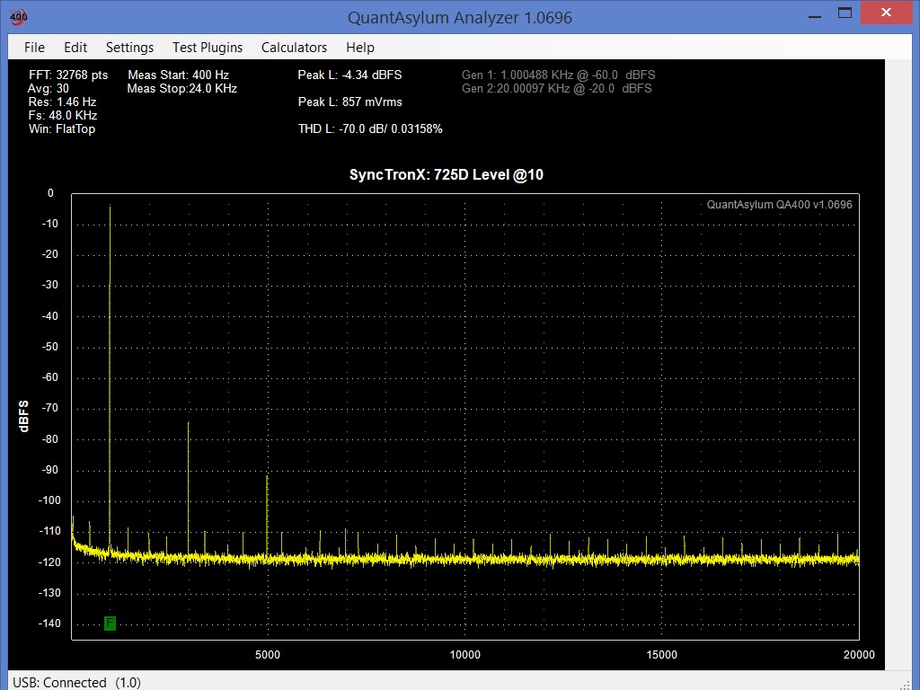
1kHz from HP339a Oscillator to unbalanced input
of Shibasoku 725D, Meas Function = Level. Response slow.
Frequency 996Hz, adjusted to to 10 on the 0/1 Meter Range.
Meter @ 10.
I assume the difference is the insertion loss of the QA400?
At follows:
I'll have to figure out how to set it.
1kHz from HP339a Oscillator to unbalanced input
of Shibasoku 725D, Meas Function = Level. Response slow.
Frequency 996Hz, adjusted to to 10 on the 0/1 Meter Range.
Meter @ 10.
I assume the difference is the insertion loss of the QA400?
At follows:
Last edited:
I have the QA400.
I'll have to figure out how to set it.
1kHz from HP339a Oscillator to unbalanced input
of Shibasoku 725D, Meas Function = Level. Response slow.
Frequency 996Hz, adjusted to to 10 on the 0/1 Meter Range.
Meter @ 10.
I assume the difference is the insertion loss of the QA400?
At follows:
No it not insertion loss it's just the way they calibrate the QA400.
You have to delete the cal file in order to recal the QA400.
I don't think you'll be able to do it with the QA but give it a try.
No matter if it 3dB low we can mentally add the 3dB.
Show one in distortion mode.
Here is from the same imput, etc.
On the Normal output. The Meter Range is
set to auto, and it is on 0.003/-90dB range.
The meter indicates about .5%.
On the Normal output. The Meter Range is
set to auto, and it is on 0.003/-90dB range.
The meter indicates about .5%.
I've got multiple sessions on here with different computers.
The LapTop on the bench and the fixed PC in another room.
Recall Shibasoku talked about the noise reduction on the output.
I can't recall if we can use Monitor Trigger and then switch between
Normal and Analysis, the little button to the left of Trigger.
The LapTop on the bench and the fixed PC in another room.
Recall Shibasoku talked about the noise reduction on the output.
I can't recall if we can use Monitor Trigger and then switch between
Normal and Analysis, the little button to the left of Trigger.
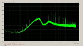
Some improvement here.
As the spike around 500Hz is brought down the harmonics generated from this clock signal
drop proportionally. I've got a 10dB improvement here so I'm going to call it a night.
I've been at it for hours. Not easy to do without a schematic. I want this signal into the noise then all the grass above will be gone.
Next step will be to reduce the distortion.
Attachments
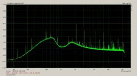
I'll be damned. Clock noise. And that propagate throughout the analyzer.Some improvement here.
As the spike around 500Hz is brought down the harmonics generated from this clock signal drop proportionally. I've got a 10dB improvement here so I'm going to call it a night. I've been at it for hours. Not easy to do without a schematic. I want this signal into the noise then all the grass above will be gone.
Next step will be to reduce the distortion.
Or is that clock noise coming through the monitor output?
or Both? Is there any benefit to getting a clock upgrade for this?
One of those radiated and hardened clocks?
What is the clock frequency?
I'll ask other questions when you get finished.
Last edited:
Poor ground routing. Unfiltered rails t noisy digital circuitry.
The 725D meets Shibasoku's spects. There was no reason for them to go further.
Not all the boards where laid out by the same person. It shows. One digital board has all the grounds looped around the parameter of the board as well as all the supply rails.
This turns the whole board into a transmitter with a dipole antenna pointing straight at the analog boards.
But the main problem is drawing current by the digital circuitry through or by the analog
circuitry. The analog ground needs to be downstream from the digital ground return currents.
Rerouting the digital ground, the clock, back to the analog ground at the analog power supply
solves this problem.
I'll be damned. Clock noise. And that propagate throughout the analyzer.
Or is that clock noise coming through the monitor output?
or Both? Is there any benefit to getting a clock upgrade for this?
One of those radiated and hardened clocks?
What is the clock frequency?
I'll ask other questions when you get finished.
The clock is about 498Hz. That's why the harmonics show up in the FFT. The clock is part of the analog divider for the meter circuit. The analog divider circuit does the THD+N calculation. It operates on a DC signal provided by the peak level detector at the output of input amplifier (impedance convertor). A peak detection is also done at the analyzer output which also supplies the signal to the monitor output. The two DC signals are ratio by the analog divider and it is the output of the divider which is sent to the meter for THD+N mode.
Not all the boards where laid out by the same person. It shows. One digital board has all the grounds looped around the parameter of the board as well as all the supply rails. This turns the whole board into a transmitter with a dipole antenna pointing straight at the analog boards.
Yep, and I know exactly the one you are talking about. Because that
loop had the manual scrapes of solder mask to enable the ground to
the back panel. If it's the one I'm thinking off. I noticed and wondered
why it went around the board. Were they thinking of that loop
around an op-amp but instead thought, lets do it around the
whole board?
One board, didn't even come with a back shield panel.
But the main problem is drawing current by the digital circuitry through or by the analog circuitry. The analog ground needs to be downstream from the digital ground return currents. Rerouting the digital ground, the clock, back to the analog ground at the analog power supply solves this problem.
When you move the analog ground down steam (or rerouting the
digital ground, the clock back to analog ground at power supply) can you add say a 100 ohm resistor at each end to isolate/float analog ground, giving it
a different potential? Or can you do that with the digital ground giving
it different potential?
It meets spec. Why bother with a "redesign" if it just meets spec or
almost the same spec, they aren't that much different.
If it isn't substantially better they wasted a lot of money.
No Resistor. Just a hunk of wire will do.
If you're missing a back panel then it been removed.
That was not left off by Shibasoku.
If you're missing a back panel then it been removed.
That was not left off by Shibasoku.
What's strange is there was never a mark on the board where
there would have been screws, those holes are the only ones
in the analyzer that aren't reinforced with rings around around
the screw holes like the other boards.
I can't figure that one out. I wonder if it performs better with out
the back plate. Mine's had a long history of calibration so it couldn't
have not met spec. BUT, it doesn't mean it won't be nosier
or couldn't be improved upon.
Maybe the board with the bipolar antenna was meant
to replace one of the board backs? NOT.
Last edited:
What's strange is there was never a mark on the board where
there would have been screws, those holes are the only ones
in the analyzer that aren't reinforced with rings around around
the screw holes like the other boards.
I can't figure that one out. I wonder if it performs better with out
the back plate. Mine's had a long history of calibration so it couldn't
have not met spec. BUT, it doesn't mean it won't be nosier
or couldn't be improved upon.
Maybe the board with the bipolar antenna was meant
to replace one of the board backs? NOT.
The back plate PCB misalignment was a screw up. The back plate cant come in contact with the chassis so it has to be smaller than the board. You can see where new holes where drilled and solder mask scrapped away to contact the back plate stand offs to the board ground.
The back plate on the A6 board is not grounded. if you ground it to another boards back plate a big chunk of noise will disappear.
The A6 digital board is right beside analog filters on the A5 board with no shielding between.
Maybe the board with the bipolar antenna was meant
to replace one of the board backs? NOT.
Dipole antenna Sync.
Just bad practice. The boards are not usually done by engineers.
I just undid my stack of equipment, of course the 725D was at the bottom.
Thank you David, dipole antenna.
Opened her up. Whoa, my memory is failing me.
Proper descriptions follow.
And pics quickly.
A4 board, has the hand scraped rings,
but not the dipole.
A5 Board is standard.
A6 Board has the dipole I see the ring through the board,
AND
A6 Doesn't have the backing plate on it.
It also explains why every board in my 725D also has
two sets of screw holes on every corner.
Shibasoku didn't think it through out properly. I'm guessing
they just designed the boards from the prior model...725B/C.
On those boards, they have the tongue sticking out of the bottom
with the contacts...so the back plate would have been okay for that,
assuming the 725C is that way. The 725D it wouldn't work so they
had to redo the boards or modify the prior board stock with different
holes.
After what you just posted I'll have to make a back plate for it.
I'm sure a ready made plate would exceed my budget.
Note: with the new Microsoft update to the operating systems.
I can no longer delete pics in my devices (cameras, phones, etc)
because Windows wants you to copy AND automatically delete
rather then just selecting say 10 pictures in your camera and
manually deleting them. Holy smokes micromanaging now
how everyone's files are...it will only get worse.
Here is the pic inside my 725D:
Last edited:
It's very likely Shibasoku doesn't do the manufacturing. Just the design and sales.
Like HP.
The boards were done by different layout guys. It shows.
The 725D is a completely different design from the 725B/C.
The boards are longer and house twice as much circuitry. The card edge was replace with back plane headers and pins.
A Twin T was used for the first BEF (band eliminate filter). The 725B/C used a bridged T.
Last edited:
Here are two more pics:
Here is the fix for the cap that broke:

Is this where you describe the dipole antenna on the A6 board
the back sides of boards in post #336?
Here is pic of the back side of the boards:

Here is the fix for the cap that broke:
Is this where you describe the dipole antenna on the A6 board
the back sides of boards in post #336?
Here is pic of the back side of the boards:
Last edited:
Yes,
Not a problem as long as I have the camera working and kid
or mom doesn't run off with it or the interface cable. ; )
Do you want a pic of the A5 board looking down?
or the whole back of the A5 board pulled.
Solid or Transparant?
I can back light it so if you want to see through
the board a little bit you can.
I'm going to go to my parts store and buy some stock and
cut it to fit, to make a new back board.
I don't think they have aluminum in stock.
They do have sheet's of copper, actually
foamed core copper sheeting. That might
even be better for shielding. Did you just
run a wire from A6 ground to A5 ground or A7?
or elsewhere in the unit.?
- Home
- Design & Build
- Equipment & Tools
- ShibaSoku Automatic Distortion Analyzer