Perhaps it would be useful to make an effort to understand why the circuit oscillates at 214 kilohertz and not some other frequency. (214 is the geometric mean of 200 and 230, which are the boundaries of the confidence interval of my eyeballing the scope wiggles #489)
What kinds of circuit misbehaviors might result in oscillation at 0.214 MHz? What kinds of misbehaviors could not possibly oscillate at 0.214 MHz?
A theory which contradicts the measured data is not a source of great comfort ... so, I suggest, it may be a good idea to find a theory which agrees with the measured data. Measurements say the circuit has high-Q oscillatory ringing (Q=8.3 ; zeta=0.06) at 0.214 MHz.
Okay so I am at a bit of a loss...
Are the scope shots above really merely showing me the impact of the trace inductance in the board, output caps and, much more significantly, wiring to and from the chop chop box and load resistor?
Is the latter completely obscuring any further analysis? I see the same thing on my scope screen even when I power the op amp and Vref from Vout.
Do I simply take some comfort that it didn't go completely unstable and move forward or do I have a real circuit problem (and perhaps should ditch the entire project!)?
I can model the circuit and see good phase margin, good transient response (except for the impact of output cap ESL) etc. But if I put it on the bench and can't see through the test setup wiring inductance I'm unsure what to do next.
Capacitance at the load should bear the brunt of any transient current needs...
I can tweak the board's output capacitance (smaller caps in parallel for better impedance profile, or even make any further iteration of the board use 2.5mm spacing output caps for lower ESL) but can only do this based on desktop modelling rather than observing the impact in the physical circuit. (Powering Vref and the op amp from Vout will provide a good deal of efficiency in any further board iteration as well.)
Argh...

One way to get a clearer picture here is to measure with the scope probe directly at the point on the board where the error amp is connected, so across the two resistor divider that sets the feedback to the - input.
If that is very different from what you measure across the load, you know that at the load you see the impact of wiring etc.
When you measure at the load, try to connect a good cap directly across the load across the same points where you have the scope probe. Only then do you measure the supply as the load sees it.
Jan
What kinds of circuit misbehaviors might result in oscillation at 0.214 MHz? What kinds of misbehaviors could not possibly oscillate at 0.214 MHz?
A theory which contradicts the measured data is not a source of great comfort ... so, I suggest, it may be a good idea to find a theory which agrees with the measured data. Measurements say the circuit has high-Q oscillatory ringing (Q=8.3 ; zeta=0.06) at 0.214 MHz.
I know that both a series resonance circuit and a parallel resonance circuit will have a resonate frequency at 1/(2Pi.SQRT(LC)) Hz.
I know that for a parallel resonance circuit Q= R.SQRT(C/L)=R/XL=R/Xc. If I assume R=8 ohms (the resistance of the load across the chop chop box terminals measures closer to 8.3 Ohms but that's spurious accuracy versus the estimate of Q) , then I can solve for each of L (717nH) and C (772nF). (Of course, if I assume a value for R of 7.763 I would get the same values for L and C as you have in row 25 of the table you provided.)
And there I hit a roadblock as I can't relate these to any points in the circuit.
One way to get a clearer picture here is to measure with the scope probe directly at the point on the board where the error amp is connected, so across the two resistor divider that sets the feedback to the - input.
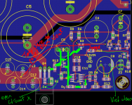
Thanks Jan. Where I have marked on the attached image?
When you measure at the load, try to connect a good cap directly across the load across the same points where you have the scope probe. Only then do you measure the supply as the load sees it.
Jan
What would, in your opinion, constitute a 'good cap'? I'm measuring right at the pads below the fasten terminals, very close to the board's output caps.
Doesn't temporarily adding a cap just shift the resonance frequency lower? Remove it and it goes back again?
Attachments
Thanks Jan. Where I have marked on the attached image?
So you are measuring at the regulator right? Assuming the load with the chop chop is some inches away? How does it look at the load, and do you have a cap at the load, like 0.1uF film? If you still see ripples at the load, try a zobel directly at the load.
Jan
That's akin to sweeping the dirt under the carpet: the problem will still be present, but it won't offend your eyes.If you still see ripples at the load, try a zobel directly at the load.
Jan
I would take the opposite approach: try to find a TP where the problem is more obvious, like the output of the opamp.
If the ringing is visible there, maybe larger than at the output, this means the problem is caused by marginal stability of the loop itself, not a local resonance caused by an unfortunate combination of passives.
If indeed it comes from the loop, it would be good idea to try a more reasonable opamp, something known to be good-natured and having a GBW product of no more than a few Mhz.
LF356 for example.
That's akin to sweeping the dirt under the carpet: the problem will still be present, but it won't offend your eyes.
I would take the opposite approach: try to find a TP where the problem is more obvious, like the output of the opamp.
If the ringing is visible there, maybe larger than at the output, this means the problem is caused by marginal stability of the loop itself, not a local resonance caused by an unfortunate combination of passives.
If indeed it comes from the loop, it would be good idea to try a more reasonable opamp, something known to be good-natured and having a GBW product of no more than a few Mhz.
LF356 for example.
I don't disagree, but the post you react to was part of several where I tried to explain that 1st is diagnostics, and that can be helped by measuring alternatively at he load, after all the wiring, and at the amp input (or rather feedback point) itself. Basically the same you are saying.
Jan
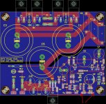
Thanks guys. I was measuring at the pads under the fasten connectors at the output of the regulator board. (Bottom left of the image in post 503.)
After reading the above comments I took a series of additional scope snapshots probing various other points in the circuit. Please see attached.
(All of the positional comments should be read in conjunction with the board image in 503. I will try to be as explicit as possible.)
1. Z3.png
This is with the rising edge of the stimulus and was taken at the anode of Z3 i.e. basically the output of the op amp. The GND spring of the probe was sitting in the GND pin connection to the lower GND plane to the right of C11.
2. Z3F.png
Same as above but falling edge of stimulus waveform (i.e load off)
3. RXR.png
Probe at left edge of Rx; ground spring at the via to the lower GND plane to the right of R13.
4. RXF.png
Same as above. Falling edge of stimulus.
5. OPAMPGND.png
Probe at the GND pin of the op amp (pin 4); ground spring of the probe at the GND pin connection to the lower GND plane to the right of C11. Falling edge.
FWIW this surprised me. Both probe and spring at ground. Same thing if I connected probe and spring to ground at various other points in the circuit e.g. the via to ground between C10 and C11 and the pin connection to the lower GND plane to the right of C11.
6. OPAMPX.png
As above except probe at the unconnected pin 1 of the op amp.
Attachments
How are the grounds of your two scope channels organized?
Is your scope earthed, and is there another PE connected on your system?
How is the waveform if you connect the tip and ground of your probe to exactly the same ground of your prototype?
Is your scope earthed, and is there another PE connected on your system?
How is the waveform if you connect the tip and ground of your probe to exactly the same ground of your prototype?
How is the waveform if you connect the tip and ground of your probe to exactly the same ground of your prototype?
Good one.
Edit: this type of measurements are of technical interest but have hardly any bearing on the actual use of the supply.
A more practical measurement would be with the test square wave rise/fall times reduced to say 10uS. Still very much faster than anything you will ever see in audio, but much closer to reality than sub-1uS rise/fall.
Jan
Last edited:
Hi. See post 492 for a pic. Channel 2's probe is connected to the chop chop box with it's GND connected there as well. I trigger from Channel 2. Channel 1 is probe and spring placed on the reg board.
My scope should be earthed. It is a standard UK 3 prong plug into a 5 socket extension (in turn connected to wall socket).
Another PE?
See attached three waveform pics:
1. scope channel 1 probe sitting idle on desk
2. GND spring only placed on GND pad at output of regulator (probe tip in air)
3. both spring and tip placed on the same pad
Attachments
Well, that's probably the main cause (if not the only one) of your troubles:Hi. See post 492 for a pic. Channel 2's probe is connected to the chop chop box with it's GND connected there as well. I trigger from Channel 2.
The ground connection of the chop-box is subjected to the current transients, and the resulting voltage is applied between the grounds of your two probes. They probably drop each a more or less equivalent voltage, and most of this voltage appears on the inputs, because of the finite coupling between the sleeve and the inner conductor and the non-zero screen cutoff frequency.
In such instances, you should ground one channel only, the most sensitive one, and leave the ground of the trigger channel unconnected.
When you absolutely need two sensitive channels with two different reference potentials, there are remediation means, but here you don't need them: just eliminate the ground loop.
Protective Earth: it is yet another way to create ground loops.My scope should be earthed. It is a standard UK 3 prong plug into a 5 socket extension (in turn connected to wall socket).
Another PE?
From your third pic, it seems you have a problem with the PE, or at least a common mode one (I assume the channel 2 is completely disconnected)See attached three waveform pics:
1. scope channel 1 probe sitting idle on desk
2. GND spring only placed on GND pad at output of regulator (probe tip in air)
3. both spring and tip placed on the same pad
Last edited:
For a moment I was thinking it was that simple. I removed the alligator clip from probe 2 and everything looked rosy. No oscillation at all. I thought I was home free....until I thought about it some more and realised what I was seeing - no trace of transient response - couldn't possibly be right.
So I went back and did everything again. No easy joy.
First two pics are from the op amp output, rising then falling load (100mV vertical resolution). Next two are from the pads at the output (50mV resolution). Last is the from the output (rising load) at 10mV per division.
Oscillation still appears to be around 220-230kHz.
(Note, I still have the board rigged to power the op amp and Vref from Vout.)
I still had channel 2 connected to the chop chop box and was triggering off this.
So I went back and did everything again. No easy joy.
First two pics are from the op amp output, rising then falling load (100mV vertical resolution). Next two are from the pads at the output (50mV resolution). Last is the from the output (rising load) at 10mV per division.
Oscillation still appears to be around 220-230kHz.
(Note, I still have the board rigged to power the op amp and Vref from Vout.)
From your third pic, it seems you have a problem with the PE, or at least a common mode one (I assume the channel 2 is completely disconnected)
I still had channel 2 connected to the chop chop box and was triggering off this.
Attachments


Last edited:
Back to loop issues then: 220~230KHz must be the unity-gain frequencyFirst two pics are from the op amp output, rising then falling load (100mV vertical resolution). Next two are from the pads at the output (50mV resolution). Last is the from the output (rising load) at 10mV per division.
Oscillation still appears to be around 220-230kHz.
Yup. At least now I am now more clearly seeing the impact of changes to circuit components. Thanks.
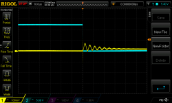
I embedded in the board layout a couple of tools to play with. (1) Zobel, Cz and Rz, from drain to gate versus (2) gate stopper resistor R12 and (3) compensation cap Cy around the op amp (from the inverting pin to output) and (4) resistor Ry in series with Cy.
You commented with respect to (1) and so recently I have used a gate stopper resistor of, currently, 47 Ohms. What I find very odd thus far is that I can change the level of damping by adding resistance in series with my compensation capacitor, but altering the size of the compensation cap Cy (none->47p->100p) doesn't seem to change the frequency of oscillation. In contrast, the LTspice model suggests a UGF of 1.2MHz with no Cy and 212kHz with Cy=100p, i.e. rather significant impact (and decent phase margins in all cases).
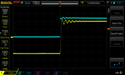
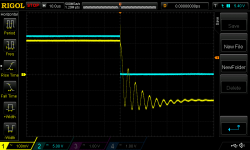
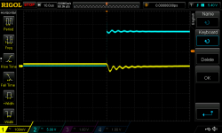
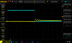
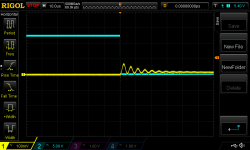
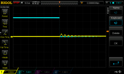
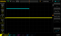
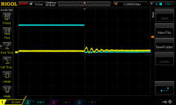
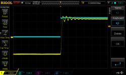
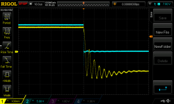
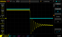
For example, see the attached 3 scope shots measured with a falling load and at the op amp output. All 3 are with a 47R gate stopper resistor. The first is with no Cy compensation. The second is with Cy=47p and Ry=7.5k. The series resistance would seem to dampen the oscillation but it seems about the same frequency. The third is with Cy=100p and Ry=0R jumper. Ordinarily I might conclude from this that compensation of the op amp is unlikely to cure the oscillation. I'm going to try increasing the gate stopper resistor and see what what impact that has.
I embedded in the board layout a couple of tools to play with. (1) Zobel, Cz and Rz, from drain to gate versus (2) gate stopper resistor R12 and (3) compensation cap Cy around the op amp (from the inverting pin to output) and (4) resistor Ry in series with Cy.
You commented with respect to (1) and so recently I have used a gate stopper resistor of, currently, 47 Ohms. What I find very odd thus far is that I can change the level of damping by adding resistance in series with my compensation capacitor, but altering the size of the compensation cap Cy (none->47p->100p) doesn't seem to change the frequency of oscillation. In contrast, the LTspice model suggests a UGF of 1.2MHz with no Cy and 212kHz with Cy=100p, i.e. rather significant impact (and decent phase margins in all cases).
For example, see the attached 3 scope shots measured with a falling load and at the op amp output. All 3 are with a 47R gate stopper resistor. The first is with no Cy compensation. The second is with Cy=47p and Ry=7.5k. The series resistance would seem to dampen the oscillation but it seems about the same frequency. The third is with Cy=100p and Ry=0R jumper. Ordinarily I might conclude from this that compensation of the op amp is unlikely to cure the oscillation. I'm going to try increasing the gate stopper resistor and see what what impact that has.
Attachments

why do you use such an insanely fast (50MHz) opamp? Either you have to kill most of its bandwidth, or make sure that everything inside the loop behaves smoothly and predictably up to 50MHz+, and this includes the power part of the circuit.
If indeed it comes from the loop, it would be good idea to try a more reasonable opamp, something known to be good-natured and having a GBW product of no more than a few Mhz. LF356 for example.
Back to loop issues then: 220~230KHz must be the unity-gain frequency
I feel the queasy vibrations of Cognitive Dissonance when I read these. The third statement feels incompatible with the first two statements, at least to me. Discordant. Inharmonious. Contradictory.
(Thinking out loud and risking foot in mouth...) Is there a way to determine from the waveform whether the oscillation is series as opposed to parallel resonance?
BTW increasing the gate stopper resistor did nothing except to attenuate the degree of oscillation, i.e. increase the dampening, slightly.
BTW increasing the gate stopper resistor did nothing except to attenuate the degree of oscillation, i.e. increase the dampening, slightly.
For a moment I was thinking it was that simple. I removed the alligator clip from probe 2 and everything looked rosy. No oscillation at all. I thought I was home free....until I thought about it some more and realised what I was seeing - no trace of transient response - couldn't possibly be right.
So I went back and did everything again. No easy joy.
First two pics are from the op amp output, rising then falling load (100mV vertical resolution). Next two are from the pads at the output (50mV resolution). Last is the from the output (rising load) at 10mV per division.
Oscillation still appears to be around 220-230kHz.
(Note, I still have the board rigged to power the op amp and Vref from Vout.)
I still had channel 2 connected to the chop chop box and was triggering off this.
I don't see any oscillation, I only see ringing. You abrubtly change/cut a current in a circuit with inductance and you get ringing. Its called dI/dT. The giveaway is that it dies out.
It is directly inproportion of the current rise/fall time dI/dT.
This is not a circuit problem; it's a measurement problem. You keep measuring unrealistically and you will keep seeing this. Nothing to do with the regulator per se.
Jan
Not necessarily: the trace inductance, output impedance of the MOS follower and output capacitance will form a low pass filter and heavily influence the UGF of the global loopThe third statement feels incompatible with the first two statements, at least to me.
The question may not have sense: it depends on the origin of the ringing, which remains unknown so far.(Thinking out loud and risking foot in mouth...) Is there a way to determine from the waveform whether the oscillation is series as opposed to parallel resonance?
What bugs me is the fact that the frequency of oscillation remains unchanged whatever you try.
As long as you cannot find a component or parameter that influences this frequency, you will remain in the dark.
I would try really massive (provisional) mods: completely kill the loop gain by using a series RC as a feedback of the opamp, with C=100nF and R= thevenin resistance of the feedback divider.
This will change the error amplifier into a unity gain inverter for most the frequency range.
If the problem is loop-related, it will change something.
Another massive test would be to double the output capacitance.
Try to to keep the leads of the additional caps extra-short. Then add some small series resistance to the caps. This test should be more passive-oriented.
You keep measuring unrealistically and you will keep seeing this.
How then to measure realistically? For those first two pics I was placing the probe at the anode of Z3 and the GND spring at the via to GND sitting between C10 and C11. (I get the same if I (gingerly) place the probe on the op amp output pin and the GND spring in the via to GND at pin 4 of the op amp.)
I don't want semantics to be a problem. Forgive me if I use improper terms. Perhaps I should have said 'damped resonance'.
Trying to eliminate variables....
There are three basic paths to the MFET gate: (1) via the op amp output, Z3 5V level shift (LM4040) and C9, and R12 the gate stopper; (2) around the op amp via Cy and Ry and onward as in (1); and (3) from Q3 and the current mirror. The fact that a resistor at Ry partially dampens the resonance would seem to suggest that (3) isn't the source of the problem but perhaps I am wrong? I guess I could lift Q3 again and drop a 1k resistor back in as a test.
There are three basic paths to the MFET gate: (1) via the op amp output, Z3 5V level shift (LM4040) and C9, and R12 the gate stopper; (2) around the op amp via Cy and Ry and onward as in (1); and (3) from Q3 and the current mirror. The fact that a resistor at Ry partially dampens the resonance would seem to suggest that (3) isn't the source of the problem but perhaps I am wrong? I guess I could lift Q3 again and drop a 1k resistor back in as a test.
Attachments
- Status
- Not open for further replies.
- Home
- Amplifiers
- Power Supplies
- Adventures with 5A regulated voltage circuits