I don't have a signal generator. Hence my chop chop box has a 50% duty cycle square wave with the frequency set by a pot driving an MCP1407 MOSFET gate driver. (Design courtesy of Mark, again.)
I was thinking another pot in series with the gate of the FET would act as an RC with the FET's capacitance. I have a spare pot (250mW power rating). (BTW I see Elvee embedded similar, albeit a fixed resistor than can be switched in and out, to generate "soft" and "hard" rise/fall times in his chop chop box.)
I was thinking another pot in series with the gate of the FET would act as an RC with the FET's capacitance. I have a spare pot (250mW power rating). (BTW I see Elvee embedded similar, albeit a fixed resistor than can be switched in and out, to generate "soft" and "hard" rise/fall times in his chop chop box.)
The ringing can find its origin in passives or in actives, within the loop or not, but one thing is certain: you cannot neglect it. Either your chop-chop box implementation or patching is lousy, rendering it effectively useless, or there is a problem of some sort with your reg, passive or active, and such a problem cannot be neglected if you aim at an above-average quality for your reg (otherwise, simply use a 78xx reg, at least it won't display such a disastrous behavior under the same conditions).
200KHz is a seriously low frequency, and with such a high Q, it is an elephant in the room.
You can always decide that after all, a load transient test is useless, doesn't bring useful information and is simply depressing for no good reason because it only brings bad news, but that wouldn't be my choice: at the very least, I would like to be 100% sure that the ringing is just an artifact of the test set-up, and if it is the case, I should be able to sim it with great accuracy.
If you identify the problem, you must be able to establish its effects quantitatively. If the discrepancies between your model and the measured reality are too large and cannot be reconciled, even with a stretch of imagination, you have to find something else.
I encourage you to make additional tests: one that comes to mind, to ascertain the passive origin of the problem is to disconnect the supply of the regulator circuits and replace the output voltage by a dumb, rudimentary supply: just a rectifier and filter cap supplying approximately the normal output voltage, maybe coupled by a lossy inductance of a few tens of µH, to make sure only the chop-box and reg's passives are in circuit. If you see the same kind of ringing, you then simply have to pinpoint its exact origin.
If the ringing is absent, you have to examine the active alternative
Why not exploit the Miller Effect to linearize the chop chop box's output waveform risetime and fall time?
Either your chop-chop box implementation or patching is lousy, rendering it effectively useless,
I wonder... One thing that 's very different about your chop chop box versus the one I constructed is that mine is powered by the DUT. Yours is powered by a battery and you make the comment "meaning completely floating and free of any potential, something always useful." When I first built my box Mark enquired "Does it manage not to thwack its own GND when delivering amperes of kaboom to its output?" The GND of the box is connected to GND of the reg.
Why not exploit the Miller Effect to linearize the chop chop box's output waveform risetime and fall time?
A cap from drain to gate? I was trying to think of something I could vary easily. A pot as a gate stopper can be set to zero. A cap not so easily removed. 😱
Last edited:
Well, that's what I did (optionally) in my version, but it is simply a way of masking unwanted or unnecessary (or unpleasant?) responses.Why not exploit the Miller Effect to linearize the chop chop box's output waveform risetime and fall time?
If you want the true unadulterated response, you have to use minimal transition times to excite every possible mode of oscillation. The result is rarely tidy, but at least it hides nothing. Some modes are spurious, like the one caused by the ground clip inductance, but 250KHz does normally not fall into any of the "normal" spurious category.
If I had the setup in front of me, I could probably locate the origin of the ringing within tens of minutes, or even minutes, and I am certain you could do the same, or even better (maybe you have already identified the problem), but distance troubleshooting is no easy task.
I think the problem will be solved when someone comes up with a realistic and credible sim: all the rest is conjecture and hand-waving. If you're not capable of backing your hypothesis with hard figures, they are essentially worthless.
At the moment, I have no hypothesis or figure to put forward: I am still wondering....
Well I'm no closer to discovering what is so obvious to Mark and Jan. Everything I read about RLC resonance doesn't suggest the rise/fall time of current comes into the picture. The frequency of resonance is related to the level of R, L and C only.
So.... I added the pot between the gate driver and gate of my chop chop box. I dialled in enough resistance to visually slow the rise/fall of the gate voltage to 5us and later 10us. (I was probably a little light on the former. There's probably some function on my Rigol scope that would compute and display this info more accurately.) Also, I perhaps should have tested a more extreme difference between the two.
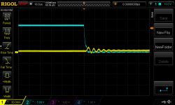
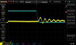
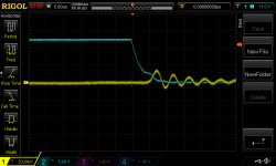
Nonetheless a new set of scope shots. All falling edge as that was most pronounced. All taken at the output of the regulator (pads under the fasten connectors). First pic is c5us fall time shown at 10us per division; second pic at 5us per division. Third pic is with the gate voltage falling over circa 10us shown at 10us per division, 4th at 5us per division.
I estimate the frequency of resonance to be about the same in both cases (I get circa 260kHz). Adding more resistance in the gate stopper increases the damping. If this is the chop chop box I ought to be able to relate the frequency back to typical component values for R and C at least...
So.... I added the pot between the gate driver and gate of my chop chop box. I dialled in enough resistance to visually slow the rise/fall of the gate voltage to 5us and later 10us. (I was probably a little light on the former. There's probably some function on my Rigol scope that would compute and display this info more accurately.) Also, I perhaps should have tested a more extreme difference between the two.
Nonetheless a new set of scope shots. All falling edge as that was most pronounced. All taken at the output of the regulator (pads under the fasten connectors). First pic is c5us fall time shown at 10us per division; second pic at 5us per division. Third pic is with the gate voltage falling over circa 10us shown at 10us per division, 4th at 5us per division.
I estimate the frequency of resonance to be about the same in both cases (I get circa 260kHz). Adding more resistance in the gate stopper increases the damping. If this is the chop chop box I ought to be able to relate the frequency back to typical component values for R and C at least...
Attachments

Last edited:
If the points that Mark and Jan are trying to make are simply that (a) it's not loop instability and (b) any circuit with R, C and L subjected to transients will exhibit resonance (damped to the degree of R) at its damping-adjusted resonance frequency, i.e. it's an unavoidable fact of life, (both of which I can agree with) then presumably the next question is whether resonance at this frequency is an issue for the application at hand. Elvee suggests it might very well be because it is relatively low in frequency. So is it advisable to attempt to shift it, perhaps by removing capacitance at the output of the regulator in an attempt to shift the resonance frequency higher? And adding extra resistance will increase the damping...
I guess the issue with this is one can't separate the chop chop box's contribution to the RCL and, of course, there are many more components to come in the eventual total chain.
I guess the issue with this is one can't separate the chop chop box's contribution to the RCL and, of course, there are many more components to come in the eventual total chain.
Last edited:
[except increasing the stopper increases the damping, but that's certainly the exception proving the rule]If the points that Mark and Jan are trying to make are simply that (a) it's not loop instability
Then, if everything is that simple, why don't you just damp this resonance to death: you simply have to add sufficient losses at the right spot.and (b) any circuit with R, C and L subjected to transients will exhibit resonance (damped to the degree of R) at its damping-adjusted resonance frequency, i.e. it's an unavoidable fact of life, (both of which I can agree with) then presumably the next question is whether resonance at this frequency is an issue for the application at hand.
I suspect you might not know where this spot is (I don't know either), but visibly Jan and Mark know precisely its location, and the amount and method of applying damping.
You'll be able to confirm that it works without any soldering, just by simulating the circuit with the values they will kindly provide.
Alternatively, you can also make a transient load test under slightly relaxed conditions, with a single frequency sinewave stimulus.
A chop-chop box won't be able to provide such a signal, but if you accept to also relax the current requirements, a 600Ω capacitor-coupled LF generator would be perfect, at 1V rms for example, to avoid putting needless stress on various elements.
I have a great confidence that this test will have a positive outcome. Good news at last
A net increase in resistance for the total circuit ought to increase the dampening of the RLC resonance.
FWIW I realised I was making a mistake when estimating the frequency of resonance above. I now estimate circa 215kHz which agrees more with Mark's initial estimate.
I also realise that when looking at the stimulus rise/fall time I'm looking at Vgs of the STP27N3LH5 of my chop chop box. A very good portion of this movement doesn't alter the current flow in the circuit because it is still more than enough to allow 1.5A to flow. So I haven't slowed the rate of change in current anywhere near as much as initially thought.
Not that any of this helps enlighten me in any way.
This boy scout is very frustrated...
Here's a piece of data: after more than 500 posts you still haven't connected the power supply to its final load.
Perhaps this means the project has proven to be too difficult for your present set of skills; you're frustrated because you don't really understand your design and you don't have a lot of debugging skill and you don't even have a debugging plan. Perhaps you're also frustrated because you have absolutely no idea what to try, while you suspect that experienced EEs could pinpoint the source of the problem in less than 10 minutes. (Elvee says exactly this in post #546).
Perhaps you're also frustrated that thread readers have become weary after hundreds of "help me" , "check me" , "tell me what to do now" requests, and so they don't feel the same urgency that you feel. You want answers and you want them now; others are not in your hurry.
Maybe you will want to step back and ask yourself whether you want to continue monkeying with your slapdash, non-PCB, uncontrolled-ground-inductance chop chop box. Un rig du merde. If not, what's next on your plan?
Everything I read about RLC resonance doesn't suggest the rise/fall time of current comes into the picture. The frequency of resonance is related to the level of R, L and C only.
Yes that is correct, the frequency of the ringing is determined by the L, R, C. The issue is that your insane dI/dT excites those R, L, C's (putting energy into it) so it then rings and of course dies out because the energy gets used up.
The rise/fall time of the current which is the dI/dT determines whether and how much energy is put into it. Less dI/dT = less energy = less ringing.
Edit: why do people put an inverse diode across a relay coil? Exact same reason - look it up!
Jan
Mark, all good points. The key source of my frustration is:
- I realise I have bitten off a lot more than I can chew and that I am enormously indebted to those helping me.
- and, yes, it is frustrating to hear that answers/solutions are obvious and could be cured in a few minutes. I have been sitting here thinking I am doing something wrong and that the thing I need to do right is obvious and immediately before me.
So my frustration is definitely with my own lack of skill. (My wife keeps saying to me 'just walk away'.)
I have come to the conclusion that this chop chop box testing is going to tell me nothing more than (a) the circuit doesn't blow up (b) doesn't go into complete oscillation and, hopefully, (c) there isn't oscillation/resonance at a frequency which could indicate low phase margin at the UGF i.e. potential instability; although frankly I doubt (c). Resonance at frequency X could come from the circuit, the chop chop box and anything in between or, rather, it will be an effect of the total of all of these together and it offers little insight to the circuit under test. Yes, I had greater expectations but now realise they were ill-founded.
So I had decided to just try to move forward with one more test using the chop chop box - one with a preload. I placed 8R as a preload and 6R as a chopping parallel load. I should have waited until I had purchased a zener to protect the supply to the chop chop box from over-voltage. I waited until Vout from the reg came up to 12V and then flicked the switch to turn on the load and chop chop box.
After about a minute it would appear likely that the MOSFET on the reg circuit went again because Vout went to 25V and 25V Vs was sent to the chop chop box. Poof.
So I am back looking at why the reg would fail with such a load. With no load attached I measure 25V at the drain (let's call this Vin) of the reg MOSFET implying Vds of 13V. A load should pull this lower due to the filter resistors (and transformer resistance etc). The reg had no problem with 1.5A continuous load or 1.5A pulsing and I had previously tested 8R||4R continuous load. I managed to grab the attached scope shot before it all went belly up so it doesn't appear things went into complete oscillation. A look at the SOA for the IPP037N06L3 G suggests it should be able to handle 3.5A continuous even with Vds of 13V. So it's a bit baffling but I guess I will figure it out. At least the chop chop box is of value with respect to (a) or perhaps it is the cause of the failure.
Attachments

Last edited:
Less dI/dT = less energy = less ringing.
Understood. Thanks Jan.
A look at the SOA for the IPP037N06L3 G suggests it should be able to handle 3.5A continuous even with Vds of 13V. So it's a bit baffling but I guess I will figure it out. At least the chop chop box is of value with respect to (a) or perhaps it is the cause of the failure.
I think if you look at those specs they probably assume an infinite heatsink or some other condition like that. But continuous 3.5A @ 13 V (being 45.5 W) definitely is not something you can do long term without some serious heatsinking. Even with a nice 2K/W sink that means 91 degrees temp rise, getting the case to 120 at 25C ambient. The chip is probably 10-20 degrees hotter...
Jan
The heat sink is rated 0.5C/W - there are two of them abutting each other as the sidewall of my enclosure. At peak UK mains the FET will dump a bit over 40W @5A according to my modelling (Vds falls well below 13V due to the filter resistors and, also, the series resistance in the toroidal transformer). Of course, the rectifier diodes will also dump some heat into the heat sink as well, about 2.25W each. The filter resistors and other will raise the ambient temp. A lot less is dissipated by the pass transistors in the other two rails and I have laid the boards out on the heat sink such that the other sink carries both of these. Plus I do not expect 5A continuous.
15 V across 8 ohms // 4 ohms during extended testing is a lot.
And the 40W is at Tcase = 25 degrees. Infinite heatsink at 25 ambient....
Jan
And the 40W is at Tcase = 25 degrees. Infinite heatsink at 25 ambient....
Jan
Last edited:
Agreed but I ran the constant load 8||4 test for about 10-15 mins; until the load resistors got rather hot. The heat sink around the FET warmed up slightly, but not much at all and seemed to be doing its job. The FET didn't fail.
I realise there's a sharp derating of power dissipation as the Tc rises. According to its data sheet the FET is still capable of dissipating 110W at Tc of 75C, 80W at Tc of 100C. I'll never ask it to dissipate much more than 40W and likely considerably less than that.
(At the moment the mobo I intend to use is powered by a single 12V supply. I inserted my basic multimeter into this to observe the current. Worst case it showed a bit over 2A, more often closer to 1.5A. Of course I don't know how that total power will be split across the three voltages when supplied that way rather than with one. I suspect the demand on the 12V will be the lowest.)
It's odd that the FET handled 4.5A for 10-15 minutes but not 1.5A->3.5A->1.5A pulsing for a very short time. Perhaps its due to my rig du merde. I'm inclined to think so but that could be a dangerous conclusion to reach.
- Status
- Not open for further replies.
- Home
- Amplifiers
- Power Supplies
- Adventures with 5A regulated voltage circuits