Solved it. On one of the channels q13 was soldered the wrong way. The other channel was fine, i just had to solder the test resistor.
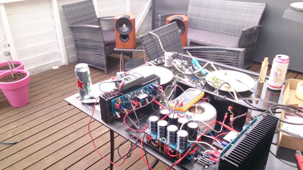
It hasn't caught fire in hours now so I think the amp is finished. 🙂
I'm impressed how it compares to my sunfire 300x2. If I had to choose one of them to keep, I would stick with the Honey Badger 🙂
It hasn't caught fire in hours now so I think the amp is finished. 🙂
I'm impressed how it compares to my sunfire 300x2. If I had to choose one of them to keep, I would stick with the Honey Badger 🙂
Solved it. On one of the channels q13 was soldered the wrong way. The other channel was fine, i just had to solder the test resistor.
It hasn't caught fire in hours now so I think the amp is finished. 🙂
I'm impressed how it compares to my sunfire 300x2. If I had to choose one of them to keep, I would stick with the Honey Badger 🙂
See , my patience paid off.
Wow , Q13. That one backwards would be the only one to make "toast"
of the whole output stage. No vbe = full current across the .22R's.
Of course - the sacrificial resistors burned (but , saved your butt).
Glad you got it.
OS
Seems like I messed up one of the channels. When listening to music I heard sparks from one of the output transistors. I measured 100v between the heat sink and v-
When I try to Ohm between the heat sink and v+, v- and gnd there's no shorts.
I measured 10k ohms between the heat sink and the metal tabs on Q16-18.
What is the minimum resistance I should have between heat sink and metal tabs?
After playing around with the mounting and increasing the resistance between heat sink and Q16-18 to ~500kohm I tried to apply the power again. Q16 started smoking and I shut off the power. Q16 wasn't laying flat on the heatsink, would that be enough to overheat in a few seconds?
After that I installed Q16 properly and powered up with the test resistors in place. They burned up in a few seconds. I suspect that I have damaged the output transistors.
How can I check if the transistors are good or bad? Can it be done when they are installed or do I have to desolder them first?
Seems like I messed up one of the channels. When listening to music I heard sparks from one of the output transistors. I measured 100v between the heat sink and v-
When I try to Ohm between the heat sink and v+, v- and gnd there's no shorts.
I measured 10k ohms between the heat sink and the metal tabs on Q16-18.
What is the minimum resistance I should have between heat sink and metal tabs?
After playing around with the mounting and increasing the resistance between heat sink and Q16-18 to ~500kohm I tried to apply the power again. Q16 started smoking and I shut off the power. Q16 wasn't laying flat on the heatsink, would that be enough to overheat in a few seconds?
After that I installed Q16 properly and powered up with the test resistors in place. They burned up in a few seconds. I suspect that I have damaged the output transistors.
How can I check if the transistors are good or bad? Can it be done when they are installed or do I have to desolder them first?
Was it the channel you had your first problems with (Q13) ?
Yes , not having one of the outputs tightened will cause it to quickly
overheat (1 second) because it will draw all the current (thermal runaway).
Usually the best practice with a output stage failure is to
replace the whole deal - drivers and outputs.
The "burnout" will stress all the others , making the likeliness of future failure
much greater. On top of that , a replacement won't be from the same group
as the originals , and may be different electrically.
Don't feel bad , I've done it. NJW's are @ 2$ each -cheap. A 12$ mistake,
but valuable lesson.
OS
s it was the same channel. I ordered 10 x njw0302, 10x njw0281, 3x MJE 15032G and 3x MJE15033G so that I can replace all transistors on the heat sink and have spares In case I burn them again. I already have spares for Q13.
I measured 10k ohms between the heat sink and the metal tabs on Q16-18.
What is the minimum resistance I should have between heat sink and metal tabs?
Before your ground is connected there shouldn't be any continuity between the heat sink and any connection on the board.
Before your ground is connected there shouldn't be any continuity between the heat sink and any connection on the board.
Correct , but if it is grounded you will see continuity temporarily as you charge
the decoupling caps. Infinite after that . No ground - infinite.
OS
How can I check if the transistors are good or bad? Can it be done when they are installed or do I have to desolder them first?
Uninstalled , on the DMM diode test ....
POS to B , NEG to C/E .6xx - .7xx to-220 .5xx on outputs.
Between C-E should be infinite (NPN)
reverse this for PNP.
OS
Seems like Q16 released all it's magic smoke. I uninstalled it and put it in the transistor tester. That way I discovered that the tester enter self test when shorting all three legs.
I have uninstalled the boards on both channels and trimmed the edge on the transistor mounting holes with a 6mm drill to reduce the risk of short circuits. Also I ordered some thermal paste that has electrical resistance in it's specifications to use on both channels when I replace the transistors. I no longer trust Arctic Silver since they don't specify it's electrical resistance. I suspect that it might be slightly conductive after curing since the transistors was shorted to ground over night while the amplifier was switched off.
I want to thank you Ostripper developing this great amp and sharing it with the public. I have learned a lot from building it and now I learn even more when troubleshooting and repairing. This is so much more fun then buying an expensive amp off the shelves.
When the amplifier are finished and stable I want to build a pre-amplifier for it. There are so many different designs out there. Can you guys help me choose what type to build? I only need two analogue inputs and a remote volume control.
Last edited:
Seems like Q16 released all it's magic smoke. I uninstalled it and put it in the transistor tester. That way I discovered that the tester enter self test when shorting all three legs.
I have uninstalled the boards on both channels and trimmed the edge on the transistor mounting holes with a 6mm drill to reduce the risk of short circuits. Also I ordered some thermal paste that has electrical resistance in it's specifications to use on both channels when I replace the transistors. I no longer trust Arctic Silver since they don't specify it's electrical resistance. I suspect that it might be slightly conductive after curing since the transistors was shorted to ground over night while the amplifier was switched off.
I want to thank you Ostripper developing this great amp and sharing it with the public. I have learned a lot from building it and now I learn even more when troubleshooting and repairing. This is so much more fun then buying an expensive amp off the shelves.
When the amplifier are finished and stable I want to build a pre-amplifier for it. There are so many different designs out there. Can you guys help me choose what type to build? I only need two analogue inputs and a remote volume control.
Arctic silver !!!! Whoa , this is not a PC. Arctic silver is conductive !
NO Arctic silver - BAD !!! (strait ZNO paste only)
PS - Kapton insulators need no grease ,or just a minute amount ... (best).
OS
Arctic Silver was what I had at hand from the years with overclocking and watercooling. I have allways thought that it was conductive.
When i was about to install the heat sinks and i realized that I didn't have any thermal paste except from AS. I googled it and read on AS' website that it was none conductive . I was a fool and trusted the marketing.
When i was about to install the heat sinks and i realized that I didn't have any thermal paste except from AS. I googled it and read on AS' website that it was none conductive . I was a fool and trusted the marketing.
Heatspreader on a AMD/Intel CPU is not at any potential (floating).
Even on the CPU's , sloppy conductive thermal interface jobs = poof !!
Amp outputs are at rail (>50V) - full current. Same thermal "goal" , different
workings.
OS
Even on the CPU's , sloppy conductive thermal interface jobs = poof !!
Amp outputs are at rail (>50V) - full current. Same thermal "goal" , different
workings.
OS
What's the best non-conductive paste to use sparingly with a semiconductor insulator, yet well sealed for thermal transfer? Is ZNO paste a commercial brand name, or should I just use Desitin? 😉Arctic silver !!!! Whoa , this is not a PC. Arctic silver is conductive !
NO Arctic silver - BAD !!! (strait ZNO paste only)
PS - Kapton insulators need no grease ,or just a minute amount ... (best).
OS
What's the best non-conductive paste to use sparingly with a semiconductor insulator, yet well sealed for thermal transfer? Is ZNO paste a commercial brand name, or should I just use Desitin? 😉
120-2 WAKEFIELD SOLUTIONS Thermal Joint Compounds | 00Z1245 | Newark element14 Canada
Thanks j. Just what I needed.
Artic silver is NOT conductive, it is capacitive. That said it should not be used for our heatsink applications. It was designed for CPUs.
I've tested it with my DMM and it's not conductive. Test it for yourselves.
Ron
I've tested it with my DMM and it's not conductive. Test it for yourselves.
Ron
120 is specified @ 0.735W/mC
122 is specified @ 2.5W/mC, this is more than 3times more conductive.
All the others are in the range 0.5 to 1.154W/mC
122 is clearly much better than the Wakefield average.
120 is specified @ 0.735W/mC
122 is specified @ 2.5W/mC, this is more than 3times more conductive.
All the others are in the range 0.5 to 1.154W/mC
122 is clearly much better than the Wakefield average.
122 is $110 for a 10cc Syringe. 122-10CC WAKEFIELD SOLUTIONS Thermal Joint Compounds | 28M8729 | Newark element14 Canada . It's definitely a better product but not really required for this application.
Artic silver is NOT conductive, it is capacitive. That said it should not be used for our heatsink applications. It was designed for CPUs.
I've tested it with my DMM and it's not conductive. Test it for yourselves.
Ron
I also did the test with DMM and found it non conductive. But I suspect that a megger would give different results.
- Home
- Amplifiers
- Solid State
- diyAB Amp The "Honey Badger" build thread