Hi Brian,
The constant expansion is from S1 to S3, then there is an increase in flare from S3 to S4. I tried to show the development (roll-out) together w/ the one from the original Keystone towards the bottom of the drawing.
Regards,
The constant expansion is from S1 to S3, then there is an increase in flare from S3 to S4. I tried to show the development (roll-out) together w/ the one from the original Keystone towards the bottom of the drawing.
Regards,
Hi Brian,
The constant expansion is from S1 to S3, then there is an increase in flare from S3 to S4. I tried to show the development (roll-out) together w/ the one from the original Keystone towards the bottom of the drawing.
Regards,
Ok. Is the bottom internal panel the ends at S3 parallel to the panel holding the driver? I'm trying to see how the increased expansion is being maintained along the length of that driver's panel to S4.
BTW - interesting use of extra space for S4-S5. Very "Danleyesque" 🙂
I am always amazed at how high a sensitivity DSL gets with their cabinets. I am still working on my horn but the best I can get with my monster is 100-101db. It is 101db at 30hz though. Anyways.....
When asked about TH gain, Danley said in one of the posts that "A few thoughts, one can get at least 9+ dB of acoustic gain (so far) over a direct radiator version using the same drive depending on the Tapped horn and driver."
Probably this has to do with the high sensitivity he gets.
But he also explained that that depends on getting the speaker with the right parameters.
When asked about TH gain, Danley said in one of the posts that "A few thoughts, one can get at least 9+ dB of acoustic gain (so far) over a direct radiator version using the same drive depending on the Tapped horn and driver."
100dB sensitivity @ 30 Hz from a reasonably-sized box is not that easy to get. Here's an idea I've been playing around with. Bear in mind that it's a 4-ohm driver (the B&C 18TBW100-4)
Attachments
Last edited:
Hi Brian,
Here is a quick picture of the angles as they ended up in the drawing. At this phase I let the numbers fall where they may, just trying to get close to the original development and frequency response; sometimes that means compromises. I went from Hornresp to a development to the drawing, your more analytical method has to be preferable, or at least much faster.
Regards
P.S.: Added my current drawing of the angles in Art's Keystone sub.
Attachments
Last edited:
Hi Y'all,
Here is a better refold of Art's Keystone than the one in Post #404, still trying to be able to provide the choice of a modified Keystone exit as well as the bottom mouth for Scientific's Carneval truck. The Keystone mouth cannot be properly simulated in Hornresp, but the bottom mouth can. I reduced the overall horn length from the first attempt, but ended up w/ a bit more internal volume, not necessarily a bad thing.
I'm attaching simulations for the bottom exit/mouth that Scientific referred to for: the latest greatest redraw of the Keystone Original, the refolded version MOD#3, MOD#3 with a bigger mouth, and MOD#3 with a maximized mouth. For fun I also mirrored the drawing to show a possible (huge) DUAL TH.
Take a look through the simulations, and see what you come up with.
Regards,
That MOD#3 drawing look sexy.Too bad it is too big for my Van
Last edited:
Here is a quick picture of the angles as they ended up in the drawing.
Ok, cool. From those angles it looks like the expansion at S4 is the same as the expansion at S1 (and therefore S3). So it looks like the TH increases expansion between S3 and part of the way to S4, then returns to the original expansion the rest of the way to S4.
There was as feature added to HornResp some time ago that allowed the driver to be placed at S3 instead of S4 for a four-segment horn. Perhaps if we look at using a constant taper from S1 to S3, placing S3 at the driver (using the "TH1" option in HornResp) and then modelling increased expansion from S3 to S4 and then from S4 to S5?
P.S.: Added my current drawing of the angles in Art's Keystone sub.
Those angles are... strange. I wonder how he came up with them? Do they make a significant difference to the FR, as compared to just continuing the same expansion from S1 to S4?
As for trying to get the same FR as the KS, bear in mind that HornResp does not do a good job of modelling it, and the FR is affected by the shape and location of the mouth along the path length. Placing the mouth across the path length is likely to produce entirely different results anyway.
100dB sensitivity @ 30 Hz from a reasonably-sized box is not that easy to get. Here's an idea I've been playing around with. Bear in mind that it's a 4-ohm driver (the B&C 18TBW100-4)
If increasing cut off to 35 Hz would bring in 2 more dbs, that would be acceptable. The rest would have to do done with equalization....once the amp has the headroom.
Yes I am planning to use 4 ohm B&C drivers.
Hi BP1Fanatic,
That DUAL @ Eg=104 2pi would just be loud. At 42Hz Hornresp has the power conversion efficiency @ 54.25%.
Regards,
That efficiency is pretty high. Like too good to be true. I read earlier that the highest one could get was 50%. Maybe I missed something.
I am always amazed at how high a sensitivity DSL gets with their cabinets. I am still working on my horn but the best I can get with my monster is 100-101db. It is 101db at 30hz though. Anyways.....
What horn are you working on? Have you shared your sims, cad plans etc. yet ?
What horn are you working on? Have you shared your sims, cad plans etc. yet ?
+1
If increasing cut off to 35 Hz would bring in 2 more dbs, that would be acceptable. The rest would have to do done with equalization....once the amp has the headroom.
Yes I am planning to use 4 ohm B&C drivers.
Increasing the output that way would mean moving Fb up a bit by reducing the path length (which would result in a smaller box), and Fb basically sets the lower limit for any EQ/boost. As is, the design's Fb is just above 30 Hz.
There's also the issue of B&C's published parameters. I got a chance to measure two of the B&C 18TBX100 drivers, and the measurements did not match the published ones. There may be a logical reason why, but it does mean that if the measurements don't match, the sims aren't going to match either.
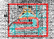
I quite like where Oliver's going with his design, though I may opt for a constant expansion through S1 to S3, and then adjusting S4 and S5 as shown in the attached diagram:
Attachments
This box looks nice and compact. I checked the dimensions - only 37.6 inches deep. Smaller than I thought it would be. And the frequency response is good. I guess increasing SPL is the hardest part, but so far things look encouraging.Here's an idea I've been playing around with.
This box looks nice and compact. I checked the dimensions - only 37.6 inches deep. Smaller than I thought it would be. And the frequency response is good. I guess increasing SPL is the hardest part, but so far things look encouraging.
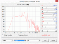
I've run a few more sims. Getting that single-taper design with that driver to go over 100dB/2.83V in any meaningful way in the middle of its passband seems almost impossible. Looks like a dual-taper TH (like the TH18, or perhaps Oliver's mod'd KS) would have to be used for that purpose.
Didnt mean to derail from you, TB and Brian I was just mentioning the high sensitivity of DSL's designs.What horn are you working on? Have you shared your sims, cad plans etc. yet ?
As Brian said having a reasonable size cabinet and 100db sensitivity at 30hz is not always easy. I couldnt do it but I am sure others can. I was looking at building a BC218 type of cabinet. I cant get the SPL that DSL gets but its high enough for me and I have the drivers already. So for me reasonable is no bigger than the BC218 external cabinet. Again sorry for off topic.
Last edited:
100dB sensitivity @ 30 Hz from a reasonably-sized box is not that easy to get. Here's an idea I've been playing around with. Bear in mind that it's a 4-ohm driver (the B&C 18TBW100-4)
cool design! How's the group delay behaving, if you have simulated it? Have you tried building it? Very nice extension and SPL for edm! In an easy to build cab
Hi Brian,
Just some notes to your Post #433:
Art kept the Keystone mouth opening purposefully small to get more low frequency extension.
Also, it looks to me that he picked an exponential expansion from S1 to S3 (thus the different angles between the divider boards), with a rapid expansion from S3 to S4 (or there abouts, around the inside top path and front corner going to the driver). I'm quite sure he did all that on purpose, and then refined the whole thing through his exhaustive testing.
Increasing the bottom exit mouth will give higher output at the middle and upper frequencies , but will loose a little at the very bottom.
I have tried to model Art's design in detail in AkAbak, but just ran out of time. I tried to apply xrk971's method for the Karlson slot to the Keystone mouth, and it will take me at least another try to get it correct. There have been small refinements in the drawings of Art's Keystone sub over the years, and I think I finally have them in my drawing. But when you are getting to the point of splitting hairs in a simulation even the braces get to be of interest. So, I don't quite know when (or if?) I'll get this done. Hornresp does not get you there.
I have not found any better T/S parameters for the 18SW115, if someone has measured them I don't think they have shared their measurements. I don't think there is any real choice but to use the manufacturer's data with these very high powered drivers. B&C may very well take some of the parameter changes @ high power into consideration for their published data?
Regards,
Art kept the Keystone mouth opening purposefully small to get more low frequency extension.
Art suggested in his thread that the shape was chosen because it provided a smoother response and more output over the pass-band, compared to a "standard" mouth. The FR graphs seem to suggest however that a bit of extension is given up in the process, when compared to a "standard" mouth placed at the correct location - see posts #23 and #24 in his thread.
Note also that he suggests that the keystone shape will offer no advantage if the mouth is perpendicular to the path rather than in line with it - see post #25 in his thread.
In summary, I don't think using a KS mouth on this implementation of a TH is going to have any practical benefit, so it may be best to optimize the design without it.
I have not found any better T/S parameters for the 18SW115, if someone has measured them I don't think they have shared their measurements. I don't think there is any real choice but to use the manufacturer's data with these very high powered drivers. B&C may very well take some of the parameter changes @ high power into consideration for their published data?
There is the possibility that B&C is quoting the "large & cold" or "large & warm" parameters from a Klippel test, but it isn't mentioned.
I may get to find out soon enough if it makes a difference - what I'm referring to at the moment as "POC5" (thought it actually hasn't been built exactly to my specifications) is ready and I should be testing out the 18TBX100 in it at different power levels soon enough 🙂.
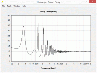
cool design! How's the group delay behaving, if you have simulated it? Have you tried building it? Very nice extension and SPL for edm! In an easy to build cab
See attached image for HornResp's GD prediction.
No, I haven't tried building it yet. Still messing around with a few sims.
Attachments
- Home
- Loudspeakers
- Subwoofers
- $325 Lab 12 based PA tapped horn ~ 35Hz extension


