Now working on input offset....
If I do correctly understand, input offset voltage is originated by beta mismatch between the two input devices.
One way to correct this would be to place a resistor between emitter and base of the bjt that has higher beta.
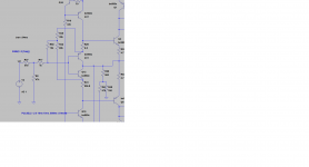
I placed a trimmer (100k) between the two emitters and bases according to the sim.
As the simulator does not help I modified one emitter resistor (R41) just to produce input offset and playing with the trimmer (R32 - R35) I am able to eliminate input offset.
Please see the sim and let me know if it should work in reality....
No, not by the beta (hfe) but Vbe mismatch between NPN/PNP pair at the input. Don't play with R41(in your schematic you set it to506.8) or adding R32,R35 and R50, it is not good way to correct input DC offset. If you must try with CCS, R4 or R7, but that could upset output DC offset. Best if you can find Vbe matched transistors pairs, Q11/Q12, Q3/Q4.
Something is very wrong with your schematic, what is R25 doing there in the feedback part?
maybe you did not understand my idea.
R25 was an experiment.... it does not exist in the real build
Also I did not play with R41 (I just modded it in the sim to be able to produce input offset)
The only important things are the 10k R50 and the 100k trimmer.
R25 was an experiment.... it does not exist in the real build
Also I did not play with R41 (I just modded it in the sim to be able to produce input offset)
The only important things are the 10k R50 and the 100k trimmer.
Attachments
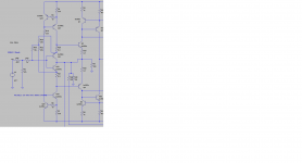
Now, following your comments I artificially created an offset by reducing R4 and could eliminate it with the right values in the R32 R35 trimmer...
This is not good way to eliminate input DC offset, in my opinion.
For some low impedance headphones the quite high output impedance could result in not the best bas.
R32 could be change from 47R to 10R and this will result in better dumping factor and better bas for that kind of headphones. Result is some increase in distortion (only for low impedance headphones).
Damir
R32 could be change from 47R to 10R and this will result in better dumping factor and better bas for that kind of headphones. Result is some increase in distortion (only for low impedance headphones).
Damir
Attachments
This problem of biasing diamonds with the disparities of the VBEs needs some work for a better solution, i think. Specially if we want to avoid any adjustable and their evils.
I'm thinking to servos, taking care of the bias of the second stage of the diamond.
Not easy to manage a way they don't fight against DC offset servo.
I'm thinking to servos, taking care of the bias of the second stage of the diamond.
Not easy to manage a way they don't fight against DC offset servo.
This problem of biasing diamonds with the disparities of the VBEs needs some work for a better solution, i think. Specially if we want to avoid any adjustable and their evils.
I'm thinking to servos, taking care of the bias of the second stage of the diamond.
Not easy to manage a way they don't fight against DC offset servo.
RCrus wants to eliminate input DC offset and thus the current trough the input biasing resistor//potentiometer. DC servo takes care of the output DC offset.
It will be possible to eliminate both DC offset in two steps, first input DC offset by manipulating input BJTs emitter resistors (adding some trim pot ) and than output DC offset with the DC servo, but in my opinion it is not so important, I mean input DC offset to be put to zero.
What i want to say is, if the first stage transistor is in the lowest range of VBE, and the second one in the hightest, the second can not turn on. (The opposite situation is less damageable).
The simple solution is to add an adjustable resistance between emitter of the first stage and the CSS. This allow ta vary the V at the base of the second, thus to set its bias. The first remain constant thanks to the CSS.
But i don't like both the requested tuning and the way adjustable resistances are aging.
What i want to say is, if the first stage transistor is in the lowest range of VBE, and the second one in the hightest, the second can not turn on. (The opposite situation is less damageable).
The simple solution is to add an adjustable resistance between emitter of the first stage and the CSS. This allow ta vary the V at the base of the second, thus to set its bias. The first remain constant thanks to the CSS.
But i don't like both the requested tuning and the way adjustable resistances are aging.
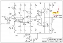
If you look carefully this preamplifier does not use diamond but a supper pairs (or as some call it Baxandall pair) and what is important here is to use transistors with low saturation voltage to allow first transistor in the supper pair to work with Vce as low as second transistor Vbe. This prevent use of the emitter resistors of higher values.
This configuration is working in Class A and all transistors are turned on all the time.
Regarding adjustable resistor aging it is possible after trimming to measure the needed values and use fixed resistor, but again I think it is not needed to do that trimming, this preamp sounds exceptional without it.
I believe the problem is very close between both of them. Anyway, forget, it is not so important.If you look carefully this preamplifier does not use diamond but a supper pairs
Trimming is not such a problem for a Diyer than matching active devices when not enough samples in stock.
Last edited:
I believe the problem is very close between both of them. Anyway, forget, it is not so important.
Trimming is not such a problem for a Diyer than matching active devices when not enough samples in stock.
Yes, there you are right.
I have been listening to the gainwire on headphones and indeed it is exceptional.
Noise is non existent, definition is very high and presence is very good with my 32ohm phones.
PS: Dadod , what do you mean by low impedance headphones ? (16 ohms ?)
Noise is non existent, definition is very high and presence is very good with my 32ohm phones.
PS: Dadod , what do you mean by low impedance headphones ? (16 ohms ?)
Good news!
My friend Valery has sent me 2sk117 as offer.
Thanks Valery!
You are welcome my friend Thimios!
I like sk117 a lot - fast, low-noise enough, works well at low currents (when required)

I have been listening to the gainwire on headphones and indeed it is exceptional.
Noise is non existent, definition is very high and presence is very good with my 32ohm phones.
PS: Dadod , what do you mean by low impedance headphones ? (16 ohms ?)
Your 32ohm goes to the low impedance headphones. My Sennheiser is 300ohm and other one AKG is 600ohm.
Thanks for your opinion about the preamplifier.
You are welcome my friend Thimios!
I like sk117 a lot - fast, low-noise enough, works well at low currents (when required)
Valery is very generous, very special guy. 😀
I had chance to do some listening of the Gainwire mkII on a better setup. And I think this pre is really something. It make my amp so much better, more dynamic and seperation, more musical ... After connect to my power amp, plug it out is un-reasonable. I also compared it to a DIY MBL and BA3, my pre win by my a clear margin. But it is a bit unfair because they used LM317 / LM337 power supply.
I'm not sure if it is the magic of Current conveyor or the buffer or the shunt power supply. But I'm happy!
I'm not sure if it is the magic of Current conveyor or the buffer or the shunt power supply. But I'm happy!
Last edited:
I had chance to do some listening of the Gainwire mkII on a better setup. And I think this pre is really something. It make my amp so much better, more dynamic and seperation, more musical ... After connect to my power amp, plug it out is un-reasonable. I also compared it to a DIY MBL and BA3, my pre win by my a clear margin. But it is a bit unfair because they used LM317 / LM337 power supply.
I'm not sure if it is the magic of Current conveyor or the buffer or the shunt power supply. But I'm happy!
Don't worry be happy!
PS. Just tell what mode you like more, NGNFB or CFA?
Don't worry be happy!
PS. Just tell what mode you like more, NGNFB or CFA?
another fine amp circuit and performance from you..... 😎🙂
THx-RNMarsh
- Status
- Not open for further replies.
- Home
- Amplifiers
- Solid State
- No NFB line amp (GainWire mk2)