part 2
Here is the thread too
http://www.diyaudio.com/forums/digi...ow-phase-noise-jitter-crystal-oscillator.html
Here is the thread too
http://www.diyaudio.com/forums/digi...ow-phase-noise-jitter-crystal-oscillator.html
Attachments
Last edited:
The problem is the flux. Zero crossing point varies in time because the noise. So, the best is to liberate us from-it.From your waveforms shown, zero crossing would be a good starting point as well.
By example, we can use a FIFO and a clock as perfect as possible.
The process is to record the flux. Independently, read the first bit, then wait for the next edge of our low jitter clock to build the pulse.
I hope i'm clear enough to be understood even with people having no idea of the process.
There is a thread in diyaudio, where the op put together a low phase noise osc & had a group buy. The guy from Italy, selected Laptech as the crystal supplier. That rang a bell as it is a local supplier who we selected, to buy our crystals, for fibre optic comm systems we were designing.
Find attached the info from that thread.
Do you know of a distributor for Laptech crystals or is it manufacturer direct only?
I believe they are mfg direct, but the op of the ref thread said they had a min qty of 5-6 IIRC. Send them an email or phone them to find out.
Also as "Esperado" was explaining, "iancanada" has a thread on asynch FIFO for this application.
http://www.diyaudio.com/forums/digi...project-ultimate-weapon-fight-jitter-356.html
Also as "Esperado" was explaining, "iancanada" has a thread on asynch FIFO for this application.
http://www.diyaudio.com/forums/digi...project-ultimate-weapon-fight-jitter-356.html
I believe they are mfg direct, but the op of the ref thread said they had a min qty of 5-6 IIRC. Send them an email or phone them to find out.
Also as "Esperado" was explaining, "iancanada" has a thread on asynch FIFO for this application.
http://www.diyaudio.com/forums/digi...project-ultimate-weapon-fight-jitter-356.html
They're not far from here but the minimum quantity might turn into a problem. It would be nice to find something of similar quality that anyone could purchase easily.
I've checked out a few of Iancanadas threads. He's got lots going on.
I do not think you will be able hear nor measure this jitter concern, so I'd suggest pick a common xtal footprint or pattern in Diptrace terms and go with what is available at Mouser or Digi-key. Could offer a way to implement the FIFO idea as an option but I do not know enough of the details to offer solid advise.
I have not spent much time either following the asynch FIFO thread to understand the benefits and if they are apparent upon a listening review.
I have not spent much time either following the asynch FIFO thread to understand the benefits and if they are apparent upon a listening review.
I'm thinking of just cranking out a quick tester DAC with minimal controls just to test with. I'd like to try to stay as simple as possible with good sounding results but I don't have enough experience with DACs to wing it.
I've ordered one of Linuxworks boards as a quick tester to see if the Arduino is up to the task too. If it's too clunky I'll need to step up to a better processor but I would really like to keep it simple. Is it a huge amount of coding to write firmware for select-able display screens and controls? Some may like encoders, others may like pots. Big screen or small. Options are nice.
I've ordered one of Linuxworks boards as a quick tester to see if the Arduino is up to the task too. If it's too clunky I'll need to step up to a better processor but I would really like to keep it simple. Is it a huge amount of coding to write firmware for select-able display screens and controls? Some may like encoders, others may like pots. Big screen or small. Options are nice.
Is it a huge amount of coding to write firmware for select-able display screens and controls?
Depends on a lot of things. What you want to do and what type of display that you use. I know that Linuxworks stuff is done with a Character LCD, so that is a lot easier than doing it with a graphics LCD such as FT800. A graphics display will have significant more amount of coding, meaning more flash space requirement.I've ordered one of Linuxworks boards as a quick tester to see if the Arduino is up to the task too.
Modifying Linuxwork code to fit new features, change the UI, is not an easy task, one that requires a huge investment in time and frustration. One that i would not think is a good path to follow for a rookie, due to the confusion and available support.
The display interface can be designed to operate both a std character and FT800 type graphics display, so that can be a h/w option.
Hard for me to give advise when i do not know the feature set of your design, how you want to operate the device, "UI" look and feel etc.
One thing I do know is that avr-xmega is cheaper/faster/more-mem,features than a regular avr-mega and has a much better upgrade path. But if you want to leverage someone elses code, then it is best to stick with the same architecture/device family.
I am playing around a bit with DipTrace. All these EDA tools have their own way of doing things for sure, but the libraries are massive. I did notice all the pattern libs only have a silk screen layer and no assy layer info. they think only one layer will do, it is near- sighted.
Did you get your bootloader figured out?
Last edited:
Depends on a lot of things. What you want to do and what type of display that you use. I know that Linuxworks stuff is done with a Character LCD, so that is a lot easier than doing it with a graphics LCD such as FT800. A graphics display will have significant more amount of coding, meaning more flash space requirement.
Modifying Linuxwork code to fit new features, change the UI, is not an easy task, one that requires a huge investment in time and frustration. One that i would not think is a good path to follow for a rookie, due to the confusion and available support.
The display interface can be designed to operate both a std character and FT800 type graphics display, so that can be a h/w option.
Hard for me to give advise when i do not know the feature set of your design, how you want to operate the device, "UI" look and feel etc.
One thing I do know is that avr-xmega is cheaper/faster/more-mem,features than a regular avr-mega and has a much better upgrade path. But if you want to leverage someone elses code, then it is best to stick with the same architecture/device family.
I am playing around a bit with DipTrace. All these EDA tools have their own way of doing things for sure, but the libraries are massive. I did notice all the pattern libs only have a silk screen layer and no assy layer info. they think only one layer will do, it is near- sighted.
Did you get your bootloader figured out?
I haven't had much time to mess with the bootloader. It's loaded on a board but i need to load USB firmware before I can do anything with it.
Some of the Diptrace models have assembly files with them. The board house I use converts them to silkscreen and prints it on the boards.😕You can edit your own models and add assembly layers to top or bottom. You can copy the existing libraries to another folder and edit them as well.
Sure, I figured that much out so far and that is exactly what i did,copy to another lib and edit. It is just a first observation, that assy layer info are missing in most patterns & silkscreen layers info is there for most but it is not the same as assy layers, as I am used to using. Assy layer data is not required for pcb fab but is useful for design usage. It is a minor issue like I said.Some of the Diptrace models have assembly files with them. The board house I use converts them to silkscreen and prints it on the boards.You can edit your own models and add assembly layers to top or bottom. You can copy the existing libraries to another folder and edit them as well.
I also see a dual RCA phono conn that you can use too, CUI RCJ-2123
which is the same as
161-4219-E Kobiconn | Mouser
Good Luck
Rick
Do you plan to use WM880x ?
I'm still undecided. I've found a Cirrus device that looks good too.
1ppm Uber DAC
Might be too late to consider this one, I have lost track over the thread.
AD5791
R2R?
Not cheap thou at 60$ the shot (Mouser). But if you compare to other NOS dac’s is not expensive.
Antonio
Might be too late to consider this one, I have lost track over the thread.
AD5791
R2R?
Not cheap thou at 60$ the shot (Mouser). But if you compare to other NOS dac’s is not expensive.
Antonio
The AD5791 DAC was handpicked by Mike Moffat to design the Shiit Yggdrasil.
You may want to read some impressions for this product on HeadFi
Yggdrasil: A (P)review - Two days of paradise
Other threads are available too.
Antonio
You may want to read some impressions for this product on HeadFi
Yggdrasil: A (P)review - Two days of paradise
Other threads are available too.
Antonio
What should I be seeing for idle current on the linestage? I've got it fired up on a 27VDC supply. I have the regulator set at 15V rails and am idling around 220mA. Those pass transistors are cooking.
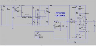
I've added some heat sink to the regulator pass transistors and did a little testing. The regulator seems to be dead stable and quiet but the slew rate of the linestage itself isn't good. Sine waves turn to triangle waves around 40khz with no load. It's designed from this schematic. Should I be adding the extra diode in the output like the diagram in post 1?
Attachments
jwilhelm:
47K || 150pF might have a bit to do with that ...
mlloyd1
47K || 150pF might have a bit to do with that ...
mlloyd1
... Sine waves turn to triangle waves around 40khz with no load...
jwilhelm:
47K || 150pF might have a bit to do with that ...
mlloyd1
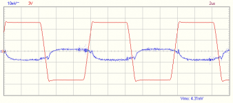
OPA177 op amp on the input is causing it. I swapped them for LT1028 an it's much better. Positive rail voltage has around 1 mV of noise on it. Negative rail has more. This is at 100khz square wave with no load..
Attachments
I've added some heat sink to the regulator pass transistors and did a little testing. The regulator seems to be dead stable and quiet but the slew rate of the linestage itself isn't good. Sine waves turn to triangle waves around 40khz with no load. It's designed from this schematic. Should I be adding the extra diode in the output like the diagram in post 1?
On the schema you posted , raise R22/16 (the CCS's) to 270-330R. That
will cool things down. You want 50-100ma class A at the output stage.
Headphones or an amp input will never load down to 47R (like I anally tested
it at) - overkill by a wide margin. 50 ma would even drive the most hungry
headphones.
I might be wrong , but the much higher Z op-amp input could work
without such a big capacitor for the filter , try 22-47pF ... we just
want to filter any RF here.
OS
270R puts the output at 75mA.
- Home
- Source & Line
- Analog Line Level
- Pitchfork pre-amplifier