Depends on priorities. Noise spec vs dynamic spec. To sacrifice mOhm spec for several Ohm spec takes some serious application specific reasoning. If the particular device (load) changes some current draw then the high Z regulator's output will modulate along accordingly. Test the device to see if its constant draw or not first.
Can't run your .asc because my LTspice is set on different component libs but If you can already produce Zo dB over AC for out then right click on V(out) curve title and make it V(out)/1A also left click just beyond y axis where a ruler symbol shows up, select linear presentation and the plot range settings also, like in this example:
Thank you , Salas


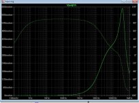
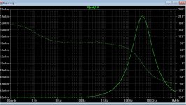
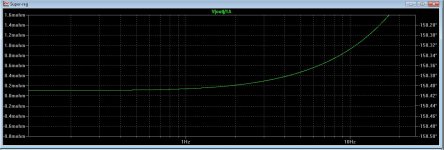
(below 1) is the Jung Zo , (below 2) is the plot with the shunt.
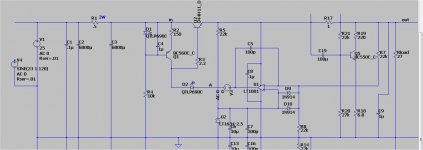
A way to avoid voltage fluctuations with the shunt is to derive the
series regulator error amp reference right at output (after the shunt).
Here , you still get
Zo fluctuations with Fc , but the voltage stays rock solid 15.082V (no
matter what !). 🙂
OS
Attachments
This is a kind of Vref sensing solution. Had to do something to avoid the obvious voltage modulation danger of course. Correct move. How is the OLG phase margin affected? Where the Zo "dune" appears some digital device may still be picky as a load or not. Its like plotting a ferrite bead with loss early in frequency by the way. Check about transient load behavior remains good. Due to large vertical scale in both plots there is not enough near zero resolution (not small enough tick) so to clearly see the base figures to the left. Are they starting at the same theoretical floor value (in mOhm)?
This is a kind of Vref sensing solution. Had to do something to avoid the obvious voltage modulation danger of course. Correct move. How is the OLG phase margin affected? Where the Zo "dune" appears some digital device may still be picky as a load or not. Its like plotting a ferrite bead with loss early in frequency by the way. Check about transient load behavior remains good. Due to large vertical scale in both plots there is not enough near zero resolution (not small enough tick) so to clearly see the base figures to the left. Are they starting at the same theoretical floor value (in mOhm)?
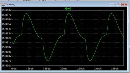
The OLG is just as good with the shunt as without. No ring .. I
modulated the output with a square wave load (below 1).
The " Dune" Fc (with the shunt) seems to be dependent on the output
capacitor value - ESR vs. freq. ... (below 2 - smaller cap).
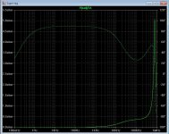
(Below 3) is the base line Zo at LF.
I want to use this (below 4) for a 5V digital supply , the shunt is to get low noise.
(below 4) specs at 5.001V / -125db psrr / 15nV/hz noise @ 250ma load.
I could just use a TI IC regulator (like everyone else) and be done with it.
BUT !! , those IC's do not even come close to those above specs.
OS
Attachments
(1) Considered good is when looking like a DC line with just little blips if the analysis cycle is long enough and the pulsed load disruptive enough for current draw.
Good luck with building the combo successfully in practice then.
Good luck with building the combo successfully in practice then.
I've got tester boards ordered for the linestage.
Yes , scope the basic Jung's on the line stage. If all is perfect ,
the digital can also be a Jung.
The 5V Jung needs a error amp that can run low voltage - TLV2322 ....
It will negotiate 3V !
OS
I've been wondering about the Jung as a digital supply too. I think it will need separate ones for the SPDIF IC though. Do the regulator ICs themselves create noise or do they just pass it through? Could we do a Jung 12V supply bus to 3V3 and 5V regulators or will that make more noise?
I've been wondering about the Jung as a digital supply too. I think it will need separate ones for the SPDIF IC though. Do the regulator ICs themselves create noise or do they just pass it through? Could we do a Jung 12V supply bus to 3V3 and 5V regulators or will that make more noise?
It seems all the TI shunts (TL431 or similar) are about 200-400nV/hz at
output.
They might be more voltage accurate than a 317 , but just as noisy.
You realize you can scale this Jung/Wenzel down .... Some apps only need
<50ma current.
Like Rsavas said , we need to itemize the current needs for the digital.
The line stage is "Itemized" - 750ma regulators powering (150ma X2 )
line stages. Plenty of leftover regulator power for any other analog.
PS - many use the TL431's for Pvdd .... will 300nV noise affect SQ (jitter) ?
Edit ... yes , the pass transistor in some of these IC's is way noisier than a BCxxx.
OS
Last edited:
It seems all the TI shunts (TL431 or similar) are about 200-400nV/hz at
output.
They might be more voltage accurate than a 317 , but just as noisy.
You realize you can scale this Jung/Wenzel down .... Some apps only need
<50ma current.
Like Rsavas said , we need to itemize the current needs for the digital.
The line stage is "Itemized" - 750ma regulators powering (150ma X2 )
line stages. Plenty of leftover regulator power for any other analog.
PS - many use the TL431's for Pvdd .... will 300nV noise affect SQ (jitter) ?
OS
I don't know enough about jitter. I think it's unequal pulse widths of the clock cycles caused by the crystal itself from the quick bit of research I've been able to do. I think the voltage supply comes into play for the jitter correction buffer that is added.
I'm still curious if there is an audible difference going NOS. I might try a test circuit at some point. I would use a buffer instead of parallel Dacs though.
I read about the jitter , it said voltage fluctuations / noise will increase
it .... but nothing about how much is acceptable.
This would be IC specific - read the DAC datasheets.
OS
it .... but nothing about how much is acceptable.
This would be IC specific - read the DAC datasheets.
OS
I read about the jitter , it said voltage fluctuations / noise will increase
it .... but nothing about how much is acceptable.
This would be IC specific - read the DAC datasheets.
OS
I think there's a lot more smoke and mirrors than actual research done with DACs. Still relatively new to the Diy crowd. I've looked at tons of designs. The only real differences seem to be interface and extra LEDs. Any sound quality modification is sketchy and poorly documented. I'm lacking proper test equipment so I can't do much proper documentation either.
JW,
This is how I would describe it. NOS equals No Global Feedback. Not literally but this is how I would compare it like using or not, in this case better error correction vs so called improvement in the sound. You decide what you think is real.
This is how I would describe it. NOS equals No Global Feedback. Not literally but this is how I would compare it like using or not, in this case better error correction vs so called improvement in the sound. You decide what you think is real.
JW,
This is how I would describe it. NOS equals No Global Feedback. Not literally but this is how I would compare it like using or not, in this case better error correction vs so called improvement in the sound. You decide what you think is real.
That's pretty much what I took from it too. It comes down to how good the error correction is. I'm really curious if it is even audible?
Not really (easy to make a good clocks) and not our problem here. The signals we receive are far to look like square waves, for a lot of reason, speed of the transmission, parasitic capacitance in cables, induced noises etc... Overshoots, rounded edges, slow slopes.I think it's unequal pulse widths of the clock cycles caused by the crystal itself
So we need to re-clock. But, with a signal as described, what point can-you take on the slope to turn your square wave 'on' when all the periods are not distorted the same way ? It is here where the noise has an influence.
I hope I'm clear enough.


Last edited:
Not really (easy to make a good clocks) and not our problem here. The signal if far to look like square waves, for a lot of reason, speed of the transmission, parasitic capacitance in cables, induced noises etc... It has overshoots, rounded edges, slow slopes.
So we need to re-clock. But, with a signal as described, what point can-you take on the slope to turn your square wave 'on' when all the periods are not distorted the same way ? It is here where the noise has an influence.
I hope I'm clear enough.
That makes sense. It sounds similar to problems in automotive ignitions. You need to select rising or falling edge triggers and thresholds to get the most accurate results. From your waveforms shown, zero crossing would be a good starting point as well.
Last edited:
JW,
Audio guys aren't supposed to understand ignition systems! 😀 That reminds me of having to read old raster patterns on a Sunnen machine. 😱
Audio guys aren't supposed to understand ignition systems! 😀 That reminds me of having to read old raster patterns on a Sunnen machine. 😱
JW,
Audio guys aren't supposed to understand ignition systems! 😀 That reminds me of having to read old raster patterns on a Sunnen machine. 😱
I'd love to find one of those old scopes.My engine shops been trying to find one for in their dyno cell for years.
There's probably a few of those old Sunnen machines in some old shops here in California. I have even seen and old distributor machine once in awhile. I still remember setting the spring tension and changing weight and welding or grinding the slot in the plate. Oh the old days. Now it is all cdi multi-spark MSD and better. I am still up in the air if I build an old school DZ302 or just spend the bucks on a late model LT1 or LT4 type of fuel injected engine. If I use the old 302 it is illegal to upgrade to fuel injection here, so stupid of them.
There's probably a few of those old Sunnen machines in some old shops here in California. I have even seen and old distributor machine once in awhile. I still remember setting the spring tension and changing weight and welding or grinding the slot in the plate. Oh the old days. Now it is all cdi multi-spark MSD and better. I am still up in the air if I build an old school DZ302 or just spend the bucks on a late model LT1 or LT4 type of fuel injected engine. If I use the old 302 it is illegal to upgrade to fuel injection here, so stupid of them.
We still do all that on the stock cars up here. No MSDs allowed in most classes. I rebuilt the engine shop's distributor machine for them 15 years ago. I tried talking them into taking my old Marquette scope at that time but they didn't think they would have any use for it. They're kicking themselves now.😀
There is a thread in diyaudio, where the op put together a low phase noise osc & had a group buy. The guy from Italy, selected Laptech as the crystal supplier. That rang a bell as it is a local supplier who we selected, to buy our crystals, for fibre optic comm systems we were designing.
Find attached the info from that thread.
Find attached the info from that thread.
Attachments
- Home
- Source & Line
- Analog Line Level
- Pitchfork pre-amplifier