"hide details" is the opposite to ringing/overshoot on fast transients.
How did you test/measure to ensure the "apparent detail" was actually in the input audio signal?
How did you test/measure to ensure the "apparent detail" was actually in the input audio signal?
Well I don´t think so.
It could as well be smearing of the signal, you know dielectric memory, where electrons are stored for a short time in the dielectricum and released with a time delay smearing fast transients.
IMHO
Koldby
It could as well be smearing of the signal, you know dielectric memory, where electrons are stored for a short time in the dielectricum and released with a time delay smearing fast transients.
IMHO
Koldby
"hide details" is the opposite to ringing/overshoot on fast transients.
How did you test/measure to ensure the "apparent detail" was actually in the input audio signal?
which bit is "I don't think so"?Well I don´t think so.
It could as well be smearing of the signal, you know dielectric memory, where electrons are stored for a short time in the dielectricum and released with a time delay smearing fast transients.........
Which overshoot/ringing/optimallydamped character is affected by the DA of the dielectric of the higher value capacitor and which is affected by the DA of the dielectric of the lower value capacitor?
And if both capacitors have no AC voltage across them, which, if either, are contributing audible distortion to the output signal?
I do not think that hiding details must be the opposite of ringing/overshoot.
I proposed another reason.
Koldby
I proposed another reason.
Koldby
so adding another DA in parallel to the sole DA changes what, to eliminate the effect of smearing caused by the original DA?
Do you realise that you are proposing a mechanism whereby using two different DA in parallel, eliminates the DA effect of both?
This question comes from:
We hear something different, therefore the output must be different.
What difference in the circuit could cause the output to be different?
This is where the hypothesis mentioned in another Thread comes in.
Come up with a possible mechanism and then find an experiment to prove the hypothesis is correct.
or simply ask the author what he measured or tested that confirms that the changed output was not simply a ringing/overshoot due to inadequately damped LC circuits formed with ultra low esr capacitors in parallel.
That's why I asked:
How did you test/measure to ensure the "apparent detail" was actually in the input audio signal?
Last edited:
"hide details" is the opposite to ringing/overshoot on fast transients.
I don't agree... it's simply due to the different type of foil used (metallized vs film/foil)
How did you test/measure to ensure the "apparent detail" was actually in the input audio signal?
I didn't measure anything.
BTW we're talking about a coupling capacitor's bypass.
Wima FKP2 and MKP1837 are phisically similar, same lead spacing (and so similar ESL) and have also similar dissipation factor at audio frequency (so also similar ESR), only aroung 100Kz the DF of the FKP2 became 10 times better.
MKP1837 5.5x7.0x7.5mm DF 0.4x10^-3 (1KHz), 0.6x10^-3 (10KHz), 4x10^-3 (100KHz)
FKP2 7.2x8.5x7.2mm DF 3x10^-4 (1KHz), 3x10^-4 (1KHz), 4x10^-4 (100KHz)
Are you really suggesting that one of them rings and the other don't?
Dario,
That is very interesting DF data. It is always hard to come by information that you can really compare, but I suspect that you are correct. All capacitors where I have seen data act as a capacitor at low frequency, transition through a resistive frequency zone, and end up as inductors at high frequency. Ideally, I would like to see impedance .vs. frequency up to 1 MHz, but dissipation factor should correlate to something similar. That is, in this case, your data shows that the MKP1837 is acting less like an ideal capacitor at 100kHz than the FKP2. To me, that suggests that they will likely sound different in an audio circuit.
While this is not a perfect explanation, I think it gives some insight into why different capacitors sound different in audio and suggests a possible way to compare capacitors by measurement. As you say, film/foil is different from metalized film. Also, how the plates are wound or stacked affects inductance. Different film materials have different dielectric memory, as Koldby suggests. Some studies have shown that at least two different modes of charge transfer are possible in capacitor dielectric materials (ionic and electron). Also, capacitor value and voltage affect the design in ways that will affect performance.
In my opinion, there are enough scientific reasons to believe that real capacitors don't act like ideal capacitors and, therefore, are likely to sound different from each other in audio circuits. That said, I have done a few experiments in trying to understand this topic and I don't think that we can define good and bad sound based on measurement, at least with what we know today. What we can do, is what you have done, that is, when data is available show that two capacitors are different in measurement and should be different in sound.
Jac
Kendeil Capacitors
Hello,
I continue to take advantage of your skills:
I have 4 capacitors KENDEIL Snap-in 50v 10000uF K05 type 30mmx40mm,
I can use them in the position C101, C102 and then save on the purchase of the current BOM?
How is their quality?
thanks
* Ivan
Hello,
I continue to take advantage of your skills:
I have 4 capacitors KENDEIL Snap-in 50v 10000uF K05 type 30mmx40mm,
I can use them in the position C101, C102 and then save on the purchase of the current BOM?
How is their quality?
thanks
* Ivan
I have 4 capacitors KENDEIL Snap-in 50v 10000uF K05 type 30mmx40mm,
I can use them in the position C101, C102 and then save on the purchase of the current BOM?
How is their quality?
Kendeil caps have good reputation for audio but, sincerely, I never tried them.
IMHO you can use them without problems.
Indeed Kendeils do sound good. I have tried them (though mine are 22000u/40V) in a "My Evolution", as well as in other projects (also HV types in tube gears).
On the Evo (where they should behave pretty similarly) they produced a warm, smooth sound, though a bit less "punchy" and "open" then other types that I've tried, namely Panasonic FH (which on the other end gave a "colder", "edgier" sound, with somewhat recessed midrange).
Currently I've got a good balance by using both types in parallel (though that would not be easily doable with the FE).
Last edited:
R13, R104, R204
Hello,
I started to populate the board, obviously with many difficulties (it was my first time with the SMD).
Now I have a doubt about the direction of R13, R104, R204; because the tutorial shows the Caddock but not the KOA.
I looked for photos on the forum but I see that they all use the Caddock, not available on Mouser ...
thanks
Ivan
Hi Ivan,
I will let Dario respond on the direction of the KOA. I'm sure the KOA resistors will be fine, but if you get the urge to go for the Caddock's, Parts ConneXion has both R13 and R104 values. In Europe, HiFiCollective has the R104 value available. Of course, there may be other sources.
It's too bad that Mouser dropped them.
Jac
R13, R104, R204
Thanks as always for the quick replies.
Surely in the future I will take the components "audiophiles" (black gate, Mundorf, Caddock, etc. etc). My aim is to build the amp with the basic version (already the highest quality) and only after doing some listening tests gradually replace the parts suggested so you can judge with my own ears and sharpen perception.
thanks again
Ivan
P.S.
if I wrote some big nonsense, is not my fault but google translator ...
Now I have a doubt about the direction of R13, R104, R204; because the tutorial shows the Caddock but not the KOA.
It's not so... but maybe it's not so clear
On tutorial's page 16 it's explained how to determine direction for axial KOAs (talking about R10), the tolerance band goes toward the direction of the arrow indicated on PCB.
Two pics from the beta thread:

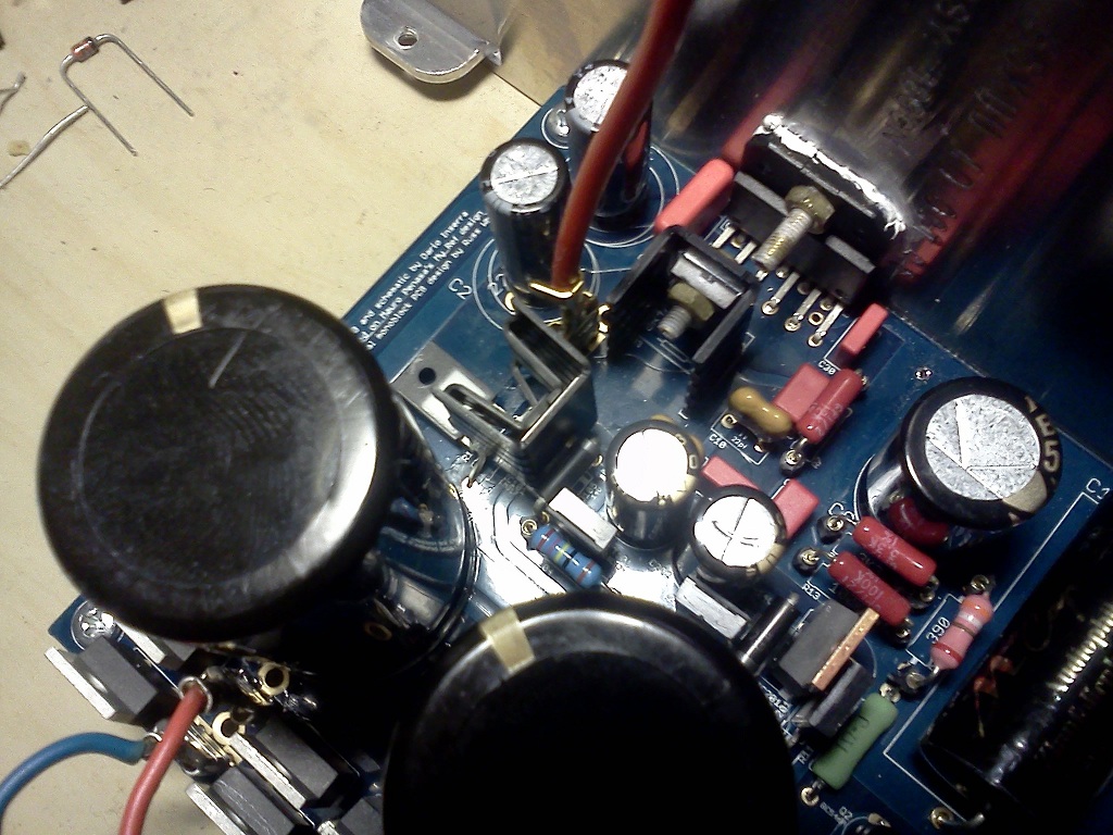
As you can see the brown tolerance band goes in the direction of the arrow.
Are there resistor that have direction?
No, as obvious, resistors are not directive, they work in both directions.
But, according my listening tests, they sound differently according direction. Some a lot, some a very little bit.
Usually in one direction sound is more 'impulsive', bigger soundstage, super-dry bass, in the other more natural, fuller and with a rounder bass (the latter is the correct direction).
Obviously we're talking about a maniacal optimization...
Thanks Dario,
They had overlooked the signs on KOAs (my bad English ..).
In the shorter I will post photos of the "creature"
greetings
Ivan
They had overlooked the signs on KOAs (my bad English ..).
In the shorter I will post photos of the "creature"
greetings
Ivan


- Home
- Amplifiers
- Chip Amps
- My_Ref Fremen Edition - Build thread and tutorial