in my case i just set the trimpot to midspan, and upon power up, i found that i need not touch it....offset was within reason....😉
Save you looking for post 531 http://www.diyaudio.com/forums/soli...honey-badger-build-thread-27.html#post3618102
Makin' me look bad Bob. 🙄
😀
Ron
Thanks for your input, Os!Matching -
From my current 5 pair experience ... with the .22R Re's - if you are within
a mV Re (15mv , for example) upon being thermally stable , Good !
All the pairs should be 14-16mv (@ 60-75ma). All will be optimally AB biased.
They will all act just like one big happy single (pair of) transistors.
If your genders ( P and N) are mismatched globally (all N's the same , all
P's the same) , the amp will just compensate through DC feedback.
This usually the case with ON/Sanken.
The only bad mismatch is one "orphan" device that will settle a few mV's
higher than the rest ... it usually is defective or has a different hfe.
It will "hog" current and possibly experience thermal runaway.
Check all 6 Re's on the badger for any discrepancies.
Most mouser MJL/NJW , if bought from the same batch (tube of 10+)
will be within that mV scenario I explained.
OS
The voltages you mention in your post, do I understand correctly that those are measured across Re? Not Vbe?
Just so I get this straight: in the case of a slightly higher voltage across one Re, is this a result of a slightly lower Vbe of that particular device, making it conduct more than the others, causing it to heat up more, thus lowering Vbe even more and you get the so-called "current hogging"?
Do I need a dummy load at the output for measuring Re's?
Yes.Just so I get this straight: in the case of a slightly higher voltage across one Re, is this a result of a slightly lower Vbe of that particular device, making it conduct more than the others, causing it to heat up more, thus lowering Vbe even more and you get the so-called "current hogging"?
That device will use more of it's temp de-rated SOAR. That device may fail before the other cooler neighbours.
a lower vbe causes the trannie to conduct less collector current Ic, this is the nature of re...to sabilise bias...
an increase in collector current increases vre and the net result is lower vbe and lower Ic,
until an equilibrium is reached....
so if all trannies are mounted on the same heatsink and close to each other, chances are they will all track...
an increase in collector current increases vre and the net result is lower vbe and lower Ic,
until an equilibrium is reached....
so if all trannies are mounted on the same heatsink and close to each other, chances are they will all track...
If the device has a lower Vbe than it's neighbours, then that device when fed with the same INPUT voltage will conduct more current. That device will show a higher Vre. That device will run hotter. That device will use more of it's temperature de-rated SOAR. That device will usually fail first since it is overloaded MORE than it's neighbours, if there is an overloading incident.a lower vbe causes the trannie to conduct less collector current Ic, this is the nature of re...to sabilise bias...
an increase in collector current increases vre and the net result is lower vbe and lower Ic,
until an equilibrium is reached....
so if all trannies are mounted on the same heatsink and close to each other, chances are they will all track...
Jamesblond for all that he is new to this worked that out when he said
and I went on to confirm that James is correct.Just so I get this straight: in the case of a slightly higher voltage across one Re, is this a result of a slightly lower Vbe of that particular device, making it conduct more than the others, causing it to heat up more, thus lowering Vbe even more and you get the so-called "current hogging"?
You are wrong.
You may recall that I often advise that device Vbe and hFE be matched at the operating current when selecting paralleled devices. That is for the reason James & I have outlined above.
Last edited:
Dan -The fuses "throttle" the outputs.
TSIP - My first projects were an ampslab project and quasi's Nmos amp. I acknowledge this amp is a little more complicated , but it can be done by a beginner.
If this is built right up to the drivers(don't put the expensive outputs in yet) and Q14/15's emitters are tied to the output (L1) with 68R resistors (temporarily omit r36) , you will not blow anything -hopefully.
Adjust R30 (Vbias) for 1.2V between the emitters of Q14-15 and this amp is ready for the outputs. I use this for OEM repairs and all my builds (frugalamp , etc) ... only fried a couple of devices with probe slips and other stupid mistakes 😱 .
OS
Hello OS 🙂
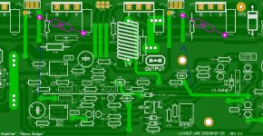
I try to "visualize" the procedures of adjusting bias using the two 68R resistors method, so it will be like this image ? and then read with DMM 1.2V between emitters, and yes no r36 on the PCB 😛 " I just want it to be sure English is my second language and I see differently sometimes jejejejeje 😀
for me any detail it is really "mucho inportante" to make sure all goes smoothly
Regards
Juan
Attachments
Hello OS 🙂
I try to "visualize" the procedures of adjusting bias using the two 68R resistors method, so it will be like this image ? and then read with DMM 1.2V between emitters, and yes no r36 on the PCB 😛 " I just want it to be sure English is my second language and I see differently sometimes jejejejeje 😀
for me any detail it is really "mucho inportante" to make sure all goes smoothly
Regards
Juan
Yes , Juan.
The two 68R's will just form a class A "buffer" with the driver devices ,
with sufficient low Z for NFB to be derived.
About 1.1-1.15V will result in 0-10ma bias per device when the outputs
are soldered in.
I even do this for repairs. NO blown outputs (unless I'm drunk 😱).
PS - NO R36 ... the 2 X 68R's replace it temporarily. 2 X 82R will also
get you "close".
OS
thanks OS, now I see it clearly 🙂 and I understand a lot better, and NO R36 of course,
I have not build many amps but I call that resistor " the gate keeper " 😛 like this image the gate keeper hands represent both ends of the resistor if he is there, he can let just some people pass by, he controls, and the key is R30 too much open and the gate keeper can't not controlled anymore the people getting in,
I just leave it like that jejejejeje I have an artistic mind OS 😛
Regards
Juan
Attachments

Make sure you put "the gatekeeper" (150R) back in before you
populate the outputs.
If your outputs DMM test OK , put a pair in .... bias the amp to
30mv between TP's. The other two pairs will bias the same.
OS
populate the outputs.
If your outputs DMM test OK , put a pair in .... bias the amp to
30mv between TP's. The other two pairs will bias the same.
OS
Yihaa! I'm finally starting to get somewhere! 🙂
the thing to remember and understand is that the emitter resistor is placed there to prevent thermal runaways as the trannie heats up making it more conductive..
the higher the value of re, the more stable the trannie is wrt to thermal runaways..
the way re works is that increasing collector currents with temperature increases the voltage drop across re, the voltage across re then subtracts to the base emitter voltage making the trannie conduct less collector current...
Make sure you put "the gatekeeper" (150R) back in before you
populate the outputs.
If your outputs DMM test OK , put a pair in .... bias the amp to
30mv between TP's. The other two pairs will bias the same.
OS
roger that
 🙂
🙂 Regards
Juan
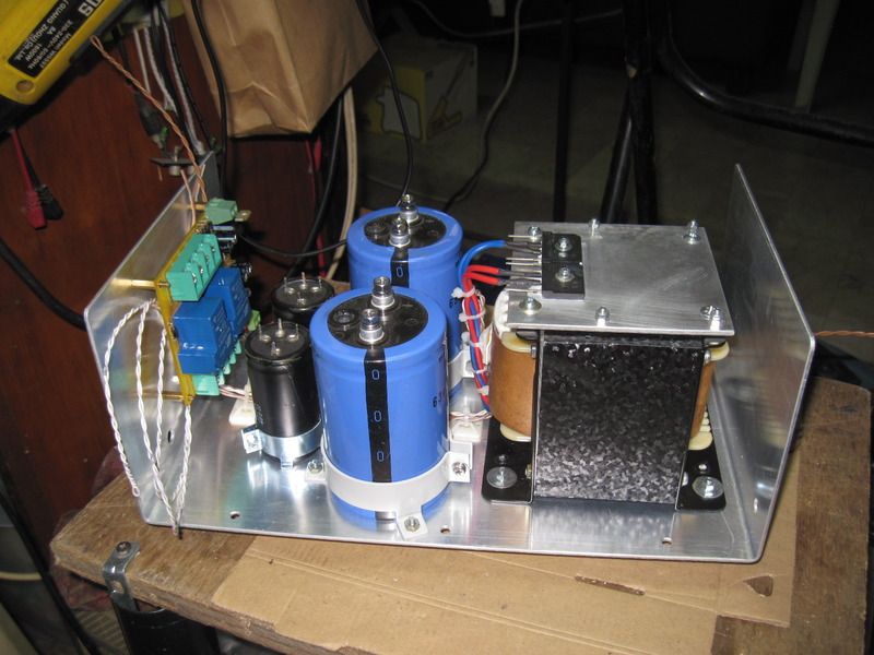
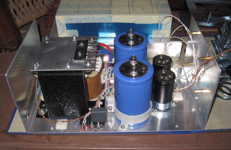
All that remains now, I guess, is deciding where to start. I have zero parts and no case to put it in. And buying everything in one go is too expensive. Maybe start with the PSU's, so that I have something to test the channels with, once they're built.
Leave the case/chassis to last.
Use a temporary heatsink during testing.
Find out how big and how many modules you want to fit in the case.
Lay them out and test them in the "shape" you intend to use.
That tells you the size of case you will need.
Typical modules for a Power Amplifier:
transformer, PSU, two Amp PCBs, soft start, DC blocker, speaker protection, auxiliary transformer, remote ON/OFF,
noise problem solved completely
Once OS suggested using freeze spray it came to my mind that I did not check how well VAS transistors were tightened to their heatsink. I became more suspicious of these when I found out that when amp gets hotter over time noise gets louder. In the meantime the other channel started to emanate some noise as well.
After dismantling the amp again I checked these VAS transistors and these got loose, not completely but enough to get overheated. So I replaced these just in case suspecting that these could have become somewhat damaged by heat (when desoldered the old ones measured well.
Having the amp dismantled I put a steel band around my toroid, replaced R27 with 75 ohm (up from 68 ohm), set the bias to 72mA and put everything back to the case. No noise, tiny hum with my ear in the speaker. With input shortened almost absolutely quiet. Connected the amp to my system and I get noise, not much but heard up to 3m from speakers.
Began to suspect electronic crossover. Disconnected interconnect at the crossover and noise is still there. Decided to replace this ordinary commercial interconnect and plugged in two I made by myself from a professional microphone cable ended with professional plugs and screen soldered to signal ground on one side. Plugged new cables in - ALL QUIET, connected crossover and switched it on - ALL QUIET, connected preamp with CD player input chosen - ALL QUIET.
I know that cables ain't cables but tell me how an interconnect, which used to work well, could deteriorate to that point without any visible traces? Gold plated plugs as new, measures well but when connected generates noise.
cheers,
Last edited:
i am building mine using a sub-chassis for the psu, it will hold most of
the psu components including the speaker delay/protector board and
the soft start boards, so then only the mains switch and power inlet needs connecting.
with it i can test the badger modules even without a final chassis...
the psu components including the speaker delay/protector board and
the soft start boards, so then only the mains switch and power inlet needs connecting.
with it i can test the badger modules even without a final chassis...


Once OS suggested using freeze spray it came to my mind that I did not check how well VAS transistors were tightened to their heatsink. I became more suspicious of these when I found out that when amp gets hotter over time noise gets louder. In the meantime the other channel started to emanate some noise as well.
After dismantling the amp again I checked these VAS transistors and these got loose, not completely but enough to get overheated. So I replaced these just in case suspecting that these could have become somewhat damaged by heat (when desoldered the old ones measured well.
Having the amp dismantled I put a steel band around my toroid, replaced R27 with 75 ohm (up from 68 ohm), set the bias to 72mA and put everything back to the case. No noise, tiny hum with my ear in the speaker. With input shortened almost absolutely quiet. Connected the amp to my system and I get noise, not much but heard up to 3m from speakers.
Began to suspect electronic crossover. Disconnected interconnect at the crossover and noise is still there. Decided to replace this ordinary commercial interconnect and plugged in two I made by myself from a professional microphone cable ended with professional plugs and screen soldered to signal ground on one side. Plugged new cables in - ALL QUIET, connected crossover and switched it on - ALL QUIET, connected preamp with CD player input chosen - ALL QUIET.
I know that cables ain't cables but tell me how an interconnect, which used to work well, could deteriorate to that point without any visible traces? Gold plated plugs as new, measures well but when connected generates noise.
cheers,
Copper can deteriorate over time. It can corrode and turn green. Strands will break from work hardening where they bend. Cheaper cable is worse for it because it doesn't seem to be annealed as well when manufactured. It will measure good with a meter but fail under load.
Good advice, Andrew! Thanks!Leave the case/chassis to last.
Use a temporary heatsink during testing.
Find out how big and how many modules you want to fit in the case.
Lay them out and test them in the "shape" you intend to use.
That tells you the size of case you will need.
Typical modules for a Power Amplifier:
transformer, PSU, two Amp PCBs, soft start, DC blocker, speaker protection, auxiliary transformer, remote ON/OFF,
Maybe I can work out some sort of modular design, like AJT's. That way I can store everything more conveniently when not building and/or waiting for parts. And it may be easier to test, tansport and assemble when finished.
I was thinking about the 5u deluxe chassis, because it looks good and is flexible in it's internal lay out. Perhaps there are other good but cheaper solutions out there.
- Home
- Amplifiers
- Solid State
- diyAB Amp The "Honey Badger" build thread