Volume Controller construction was detailed in the Wiki section of the forum.
I did my best to put lot of high res. pictures and describe every single step as much detailed is possible.
Any newbie should be able to finish this project without any issues.
Building Vicol Audio R-2R volume controller - part 1 - diyAudio
Building Vicol Audio R-2R volume controller - part 2 - diyAudio
Regards,
Tibi
Today, I spent a lot of time to find what is happening with "pop"-"click" and what ever is the name of these.
Without any sources, there is no any noise at these specific points of attenuation.
With any source (either with some dc-offset or none dc-offset) the noises are coming to my system.
I note that my system is a dac source->R2R+DCB1(buffer)->Aaron No3 Millennium Final Amplifier->Speaker.
Then, I put two bench multimeter at the input and output of R2R, nothing about dc component that means something!
Finally, I tested the R2R on oscilloscope without any input or output to find if I can capture some glitches that are meaning!
It is very difficult to catch a rapidly glitch, specially if you captured by tablet camera with different frame per second.
Anyway, I think that this issue is a relay glitch. I see that btw 32<->31dB of attenuation the glitch is much bigger than other areas that there are some small glitches.
Maybe, this issue some amplifiers filtering well, some other not filter well.
This is my opinion.
https://www.youtube.com/watch?v=abeQiqysjMc&feature=youtu.be
OK, I will add some more decoupled capacitor on these and I see if there is some improvement.
Without any sources, there is no any noise at these specific points of attenuation.
With any source (either with some dc-offset or none dc-offset) the noises are coming to my system.
I note that my system is a dac source->R2R+DCB1(buffer)->Aaron No3 Millennium Final Amplifier->Speaker.
Then, I put two bench multimeter at the input and output of R2R, nothing about dc component that means something!
Finally, I tested the R2R on oscilloscope without any input or output to find if I can capture some glitches that are meaning!
It is very difficult to catch a rapidly glitch, specially if you captured by tablet camera with different frame per second.
Anyway, I think that this issue is a relay glitch. I see that btw 32<->31dB of attenuation the glitch is much bigger than other areas that there are some small glitches.
Maybe, this issue some amplifiers filtering well, some other not filter well.
This is my opinion.
https://www.youtube.com/watch?v=abeQiqysjMc&feature=youtu.be
It is not clear for me where you want to put a capacitor. Relay coils are already decoupled with a 100nF MLC and diode.
regards,
Tibi
OK, I will add some more decoupled capacitor on these and I see if there is some improvement.
Attachments

Last edited:
Hi Lemon,
Which is the Vpp of this glitch ?
Between 31 and 32, 5 relays are changing position, switching from 111111 to 100000 and this may generate that small glitch.
Do you consider this annoying ?
Another stepped attenuators are generating huge glitches in comparison. 😉
regards,
Tibi
Which is the Vpp of this glitch ?
Between 31 and 32, 5 relays are changing position, switching from 111111 to 100000 and this may generate that small glitch.
Do you consider this annoying ?
Another stepped attenuators are generating huge glitches in comparison. 😉
regards,
Tibi
Hi Tibi,
Now, I caught the glitch very well!
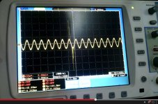
Here is the setup, that I used.
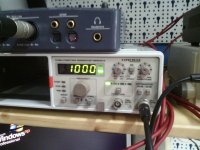
A 1KHz sinusoidal signal from a signal generator, with very low dc-offset feeds (≈0.3mV) the left channel of R2R and the Left output or R2R feeds the input of oscilloscope.
The oscilloscope was with DC Coupled at 100mV/div, at 1X full BW.
The signal at the display of oscilloscope has 148mVpp.
From what you will see, there are many significant glitches at the zone of 32-31dB of attenuation (the same are at the 16-15 zone and some very closed to 0-6dB).
I measured glitches from 300mV until to 800mVpp!
The clip = https://www.youtube.com/watch?v=h9U3-bI9DQo&feature=youtu.be
Now, I caught the glitch very well!
Here is the setup, that I used.
A 1KHz sinusoidal signal from a signal generator, with very low dc-offset feeds (≈0.3mV) the left channel of R2R and the Left output or R2R feeds the input of oscilloscope.
The oscilloscope was with DC Coupled at 100mV/div, at 1X full BW.
The signal at the display of oscilloscope has 148mVpp.
From what you will see, there are many significant glitches at the zone of 32-31dB of attenuation (the same are at the 16-15 zone and some very closed to 0-6dB).
I measured glitches from 300mV until to 800mVpp!
The clip = https://www.youtube.com/watch?v=h9U3-bI9DQo&feature=youtu.be
Attachments


Last edited:
Hi Lemon,
As far I see you are testing an older unit ?
The last version have decoupling capacitors on each relay and relays are Takamisawa.
I have measured these glitches again and beside the fact these are far outside audio band > 40KHz, are barely distinguishable and do not affect in any way audio performance. So what we are talking about ?
Regards,
Tibi
Hi Tibi,
Would the coming firmware support OLED display like your Maya project?
You can use an OLED with this VC as well.
This must have controller/com driver based on HD44780 or equivalent and work at 5V. If use one LCD back-light may need to be removed.
We didn't found one and decided to use and I2C display for Maya.
Regards,
Tibi
Group Buy still open?
PM or mail me if you are interested.
regards,
Tibi
I was one of the early adopters several years ago. The pop is there just like Lemon describes, it was also mentioned a couple of times in the old thread. In any case it is not annoying (though tastes differ) and it doesnt affect the sound but it would be good to know why it happens, be that old board or new board. We are a diy community after all and learning is what we do.
In any case this remains the best volume control i 've ever heard (or not heard)
In any case this remains the best volume control i 've ever heard (or not heard)
tsip,
This was my question as well. Are these plops annoying ?
I can barely hear them with my ear closed to speaker and my personal opinion is even these where bigger and more annoying I still prefer a stepped attenuator to any potentiometer.
I use in one of my amplifiers a DACT attenuator. This have huge plops in comparison, i can clearly hear them in my speakers and with all of this I still prefer it to any potentiometer.
So, again, what is the point to measure mV plops which are far outside audio band ? Are these affecting your speakers ? Are these affecting something at all ?
Regards,
Tibi
... it doesnt affect the sound but it would be good to know why it happens, ...
Any current that flow trough a resistor who instantly change his value, will generate a plop, or a voltage step.
Any DC parasitic current that pass through stepped attenuator will be translated in voltage.
That is Ohm law fault, not mine. 😀
To minimize this plop further you need to use very fast relays and/or use an amount of steps bigger enough to make voltage steps as low as possible. That's why we use Takamisawa. We switch them fast and in sync to keep any residual plops outside audio band.
There is also a trick implemented in firmware by danzup, maybe he want to reveal it here, or maybe not. 😉
Regards,
Tibi
Last edited by a moderator:
Before I tweaked the preamp following the r2r volume control, the pops are very loud and easily heard from 2m+ away from the speakers.
I think the difference between your setup and Lemon and myself is that you use the attenuator just before your poweramp. Lemon and myself are using it between the source and a preamp/buffer before that goes to the amp - one additional stage in between. The preamp/buffer seems to cause a small amount of DC at the outputs of the R2R vol control which causes loud pops for us.
I've come to terms that I will always hear these loud pops at those transition points until my preamp warms up (the offset changes with temperature).
All that said, I agree it doesn't impact the sound at all (if it does, it's not immediately obvious enough to me 🙂)
You can use an OLED with this VC as well.
This must have controller/com driver based on HD44780 or equivalent and work at 5V. If use one LCD back-light may need to be removed.
We didn't found one and decided to use and I2C display for Maya.
Regards,
Tibi
Tibi, Thanks a lot.
Hi Tibi,
Winstar WEH001602A is HD44780 compatible, which means I can buy it as replacement?
Yes, looks to be pin to pin compatible.
It may require a slight firmware change, but I need to buy one and test as well.
Regards,
Tibi
Before I tweaked the preamp following the r2r volume control, the pops are very loud and easily heard from 2m+ away from the speakers.
I think the difference between your setup and Lemon and myself is that you use the attenuator just before your poweramp. Lemon and myself are using it between the source and a preamp/buffer before that goes to the amp - one additional stage in between. The preamp/buffer seems to cause a small amount of DC at the outputs of the R2R vol control which causes loud pops for us.
I've come to terms that I will always hear these loud pops at those transition points until my preamp warms up (the offset changes with temperature).
All that said, I agree it doesn't impact the sound at all (if it does, it's not immediately obvious enough to me 🙂)
i am using a B1 in between as well and yes they are audible from 2m, but i have come to terms with it as well
Tibi, I like very much the R2R, but I must to find a solution to this issue because to my system isn't annoying only but I'm afraid for the tweeters.
I listen 3m far away and this glitch is audible, sometimes a lot.
Tibi, I looked to the new board and this glitch is bigger from the old one. Sometimes is bigger than 1000mV to this and more often!
Yes, I see that you have added a small smd capacitor under the diode.
I tried to find the frequency of this glitch...I have done some FFT measuring and I see when this is happening, all the Noise Floor of the FFT from 10-30KHz rise-up to the -65dB. At the other range that there is no this "pop" the rise-up of noise floor is under -100dB.
I have done a video about all of these, but first I want to put some parallel capacitors to diodes, maybe 470uF and see what will be happens.
Lemon,
Adding a 470uF over diode will mess relay switching due capacitor time to charge and discharge. You need to use far smaller cap, something under 1uF, but I think proper value will be in 1nF - 100nF range.
FFT on a step or Dirac impulse will not tell you anything. The right approach to to calculate inductor cap based on relay release and connect times. For A5W these are 6ms and respectively 4ms. And of course experiment with these values. But the most efficient is to remove any parasitic DC component.
Regards,
Tibi
Last edited by a moderator:
- Status
- Not open for further replies.
- Home
- Group Buys
- GB for R-2R Volume Controller with 4 inputs