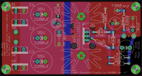
Actually I completely forgot. I made a regulated power supply and I think I have one more lying around. Just need some perf board to add another 5 parts that are extra from the original power supply (and derive 14V but should be easy looking at the old schematic). Just need to figure a way to secure it to the case.
I'm using one with the TDA7297 amplifier and works very nice.
I will need to use higher voltage rated caps on it for sure.
I'm using one with the TDA7297 amplifier and works very nice.
I will need to use higher voltage rated caps on it for sure.
Attachments
Last edited:
you can test the bias stability with a low current capability regulated PSU.
What is the quiescent current of the amplifier?
Your test PSU only needs a capability of a bit more than that.
What is the quiescent current of the amplifier?
Your test PSU only needs a capability of a bit more than that.
you can test the bias stability with a low current capability regulated PSU.
What is the quiescent current of the amplifier?
Your test PSU only needs a capability of a bit more than that.
160mA measured at fuse on the low AC side (only for power amp). Everything is soldered good on the DC side and I have a bit of work to disconnect the thicker wires. But can be done.
0.6mm diameter solid core insulated copper hook up wire has a current capacity exceeding 800mA and can easily sustain >1.5Apk, when well ventilated.
0.6mm diameter solid core insulated copper hook up wire has a current capacity exceeding 800mA and can easily sustain >1.5Apk, when well ventilated.
Ah, then I could tap the AC from the fuses after I take them out. I'll need to cobble the circuit on the breadboard but should work. Hope I have time to do it today.
I made the test with a regulated LM317 supply.
I fed in 44.5VDC and the bias on all 4 channels was at 3.7-4mA. But it was steady. Only jumping around by 0.02mA or so, because the supply was jumping by 0.01mV or so up and down. But bias seemed rock steady.
So a regulated supply for the output stage might help. I will think if it's worth it and if it can be implemented.
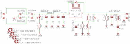
Theoretically would a LT1084 supply work? Like the one in the schematic I posted?
Recommended values for capacitors? The large cap would fall before the supply. I'd also need some capacitance after the supply, and those kind of capacitors mustn't be low esr as it throws the regulator into oscillation.
Now I'm going to look at the small signal power supply with the scope and see if it looks ok. Also I'm going to disconnect the boards that I don't need.
I fed in 44.5VDC and the bias on all 4 channels was at 3.7-4mA. But it was steady. Only jumping around by 0.02mA or so, because the supply was jumping by 0.01mV or so up and down. But bias seemed rock steady.
So a regulated supply for the output stage might help. I will think if it's worth it and if it can be implemented.
Theoretically would a LT1084 supply work? Like the one in the schematic I posted?
Recommended values for capacitors? The large cap would fall before the supply. I'd also need some capacitance after the supply, and those kind of capacitors mustn't be low esr as it throws the regulator into oscillation.
Now I'm going to look at the small signal power supply with the scope and see if it looks ok. Also I'm going to disconnect the boards that I don't need.
So it is the mains fluctuating that is altering the bias.
I'd keep it original tbh, and I'm not just saying that because its the easiest approach. I don't think you will gain anything on sonics and a high current stabilised PSU fed from the original supply can only lower headroom.
Keep it original and look for something new as a project to modify/restore etc
So it is the mains fluctuating that is altering the bias.
I'd keep it original tbh, and I'm not just saying that because its the easiest approach. I don't think you will gain anything on sonics and a high current stabilised PSU fed from the original supply can only lower headroom.
Keep it original and look for something new as a project to modify/restore etc
🙂
I just disconnected J802 from the small signal power supply. That was the feed for Dolby boards. The current decreased now to 186mA, and thus the power dissipation of the 33ohm resistor. Now it sits at a comfortable 1.15W (it's 3W rated). So I don't need to replace it anymore.
I scoped the small signal power supply and it seems quiet. My scope might pick up some noise from the line/air but that is there regardless if the amp is powered on or disconnected completely from the power outlet.
So small signal supply seems ok.
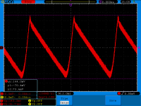
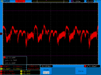
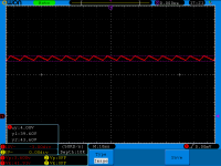
When scoping the output power supply there's ripple big time and it oscillates like crazy.
I attached some screenshots with the ripple and how it varies (AC coupled) with a horizontal time base of 500ms. Are you sure it wouldn't matter to sonics? If you say so then I'll leave it alone.
Attachments
Last edited:
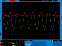
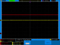
I tested the output as well.
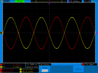
Red trace is the power supply feeding the output boards (measured at the connector on one of the output boards).
Yellow trace is the output into a 8 ohm resistor (100W). Both channels had 8ohm power resistors attached.
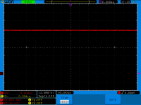
Baseline is 49.77VDC power to the output boards.
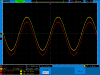
As you can see the second picture is right before clipping. 46Vpp is exactly 33 watts into 8 ohm. So those are clean 33 watts and the power supply is still 48.60VD.
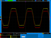
The last picture is with volume maxed out, heavy clipping, output power is 36 watts, bad ones 🙂. Still, the power supply is at 46.78VDC. So with max volume but no clipping I loose 1VDC from the power supply.
Red trace is the power supply feeding the output boards (measured at the connector on one of the output boards).
Yellow trace is the output into a 8 ohm resistor (100W). Both channels had 8ohm power resistors attached.
Baseline is 49.77VDC power to the output boards.
As you can see the second picture is right before clipping. 46Vpp is exactly 33 watts into 8 ohm. So those are clean 33 watts and the power supply is still 48.60VD.
The last picture is with volume maxed out, heavy clipping, output power is 36 watts, bad ones 🙂. Still, the power supply is at 46.78VDC. So with max volume but no clipping I loose 1VDC from the power supply.
Attachments

Oh no...scratch the last post. Forgot to push the "remote speakers" button on the faceplate. There was actually no load. Oh god, am I stupid...
And it still doesn't make sense as I connected the probe on the speaker output connector. And I see signal, with large amplitude...
Sorry for the mistakes.
I had the back knob set on 4x12 instead of 2x30 🙂 And I switched two wires and I wasn't probing correctly. Seems like there's a potential difference between the output ground speaker connector and power output board's ground connector.
I measured the baseline for the power supply with one probe. 49.62VDC with no signal.
Then I adjusted the volume right before clipping and the power supply is 42VDC RMS and has a ripple of 4Vpp.
I scoped all 4 channels and they are symmetric and looking nice right before clipping.
The nice surprise was that it puts out 45 clean watts rms right before clipping, into each channel!
Maximum volume it goes to 64 watts RMS but ... yeah.
So, what do I owe the higher wattage to? Increased PS voltage? Output transistors?
Attachments

Keep it original and look for something new as a project to modify/restore etc
Will do. Seems ok and I'm happy with the outcome, couldn't have came out better!
I'm actually preparing to start a MyRef amp project for a good friend 🙂
Ripple on the unregulated power supply is normal. Connecting a scope to the correct grounds is important in low level measurements.
If the speaker is essentially silent (no hum and noise) then there is no real issue.
Enjoy the amp for what it is... you've done a great job... don't spoil it by modifying it away from its original form.
If the speaker is essentially silent (no hum and noise) then there is no real issue.
Enjoy the amp for what it is... you've done a great job... don't spoil it by modifying it away from its original form.
You would leave them out entirely. The amplifier will be capable of driving a few k ohms down to perhaps a few hundred (from the speaker terminal or headphone jack). Just not a speaker, and be careful not to short the output as it could take out the drivers. Fortunately they are cheap and a lot of things will work in their place if you do screw up.
Kind of ironic but I did short out the outputs :/
I repaired my broken speaker. Some old Wharfedale Chevin XP2, paper fullrange. Paper got brittle and ripped. I took the speaker box, removed the driver and glued it back where it ripped. I then put back the driver in the case and put it on the shelf. I was wondering why the sound is so low on that channel because the rip was on the membrane, nothing to do with the coil area. In a few seconds the smoke came out ....
Because when I fiddled with the speaker box the bloody cables got loose and the stupid connectors are like 1cm apart!!! The output got shorted out.
Man...after all the action I blew the output transistors by shorting out the speaker....
Tho it seems that only 2 output transistors burnt. Still have 2 spares. One 330ohm is burnt, and a 0.5 ohm measures about 800Kohm 🙂
At first glance no shorts on small signal transistors.
Tomorrow I'll investigate the channel some more.
It's good as I have a mirror channel on the same board, and it's the other channel so to speak. On each board there are L+R so one is working. It helps with measurements.
It seems that the driver 2SC1384 burnt out 🙁
Also both 0.5 ohm emitter resistors and the driver's 2sc1384 emitter resistor burnt out.
Now I need to replace 2sc1384 with something.
I will thermally couple anything that works with the varistor. Will see the results after. I can't source genuine 2sc1384, only copies made by UTC.
Would prefer a modern equivalent in that spot. Even some other case style.
What would you suggest?
Earlier versions of this amp does not have the varistor.
Would a bd139/bd140 pair be a good substitute?
I know it's not perfect and I'll keep the amplifier under observation for a while but I need to replace those.
I know it's not perfect and I'll keep the amplifier under observation for a while but I need to replace those.
- Status
- Not open for further replies.
- Home
- Amplifiers
- Solid State
- to92 transistor replacement