Sorry Richard, I am so slow. I have three grandsons and some days I have to spent with them.
I Childproofed The House, but THEY KEEP GETTING IN.
🙂
-RNM
Frequency Independent Delay [isn't] NMP behaviour. It's really the trivial case.
I'd say trivially NMP but yes, doesn't matter.
However, such a delay may lead to NMP behaviour if the delays are different for the different paths.
Yes here too.
But what about Frequency Dependent Delay and one path?
That would clearly be NMP and was what I had in mind, does it exist in reality or just as a mathematical possibility?
What's the parameter?
Also there is a similar capability in the MEXTRAM models.
I checked this in the hope that a comparison of the two approaches would illuminate the shared, physical mechanism.
No luck, don't understand the MEXTRAM model.
Final point. I noticed NMP behaviour in Toni's amp and initially believed it was due to the well understood common emitter RHP zero of the VAS.
In this case, that the emitter by-pass capacitor pushed this NMP behaviour up and out of the picture.
But later I decided this wasn't the reason and Dado's amp seems to confirm it.
Instead I notice that both amps have TMC, is that the feed forward path?
Will simulate a bit more, sometime little clues reveal a whole new aspect.
Best wishes
David
Hi David,
I am trying to follow your discussion and it's not easy for me, to rusty.
I think that my amp use TPC not TMC, but it does not matter in this discussion?
Best wishes
Damir
This certainly exists and MP versions exist. From "Is Linear Phase Worthwhile? 1.7" ...But what about Frequency Dependent Delay and one path?
That would clearly be NMP and was what I had in mind, does it exist in reality or just as a mathematical possibility?
"Heyser has pointed out the concept of Group Delay does not correspond to Envelope Delay unless either the Group Delay (dO/df) or the amplitude response is constant over the whole frequency band of interest."
This is satisfied by all-pass networks but only certain types of MP functions.
The best example is IF filters for superhets where if not designed properly, there will be Frequency Dependent Delay in the passband.
These are one path and MP.
IIRC, the Engineering Memo from which the AES paper is derived shows phase measurement and Hilbert Transform of such a filter.
In fact any filter except Bessels will show this MP Frequency Dependent Delay behaviour in their passband.
I think that my amp use TPC not TMC...
I think TMC but I don't want to contradict you when it is your amp😉
There is a 2 pole network C2 & R22 & C7 (and the complementary C9 &...& C14)
And this is bootstrapped by R1 from the output.
Is this not a complementary implementation of TMC?
I am not sure if it matters yet.
Best wishes
David
This certainly exists and MP versions exist. From "Is Linear Phase Worthwhile? 1.7" ...
"Heyser has pointed out the concept of Group Delay does not correspond to Envelope Delay unless either the Group Delay (dO/df) or the amplitude response is constant over the whole frequency band of interest."
OK, I meant excess Frequency Dependent Delay.
Well... fairly sure that's what I meant.😉
Heyser's work is classic but I have never actually read it so I will track it down and remedy that.
Then I can try to write a response that uses the orthodox nomenclature.
Best wishes
David
Well those All-pass networks in "Is Linear Phase Worthwhile?" have excess Frequency Dependent Delay and I show how these lead to 'real life' Frequency Dependent Delay.OK, I meant excess Frequency Dependent Delay.
Well... fairly sure that's what I meant.😉
Heyser's work is classic but I have never actually read it so I will track it down and remedy that.
I wouldn't bother with Heyser. I spent more than a decade studying his stuff .. finally realising he was mostly pontificating from the wrong orifice.😱
IM not so HO, the only useful paper of his was the original 1967 TDS paper Acoustical Measurements by Time Delay Spectrometry
"Heyser has pointed out...''
Thanks for the incentive to track down and read his work.
I knew it was considered a classic and I can see why, whole heartedly concur.
His paper has a nice balance of perceptiveness about the physics of reality combined with mathematical depth and skill.
Quite a lot to read in the next few days.
Best wishes
David
I started on "Loudspeaker Phase Characteristics and Time Delay Distortion: Part 2" and, as you can see, like it a lot so far.
Lucky we cross posted or I may not have made the effort.
Last edited:
Could you email the ASC of the version of Toni's amp with this behaviour if its still available?Final point. I noticed NMP behaviour in Toni's amp and initially believed it was due to the well understood common emitter RHP zero of the VAS.
In this case, that the emitter by-pass capacitor pushed this NMP behaviour up and out of the picture.
But later I decided this wasn't the reason and Dado's amp seems to confirm it.
I may have it already but that was a period of furious activity. I have nearly a dozen ASCs from that period.
I can well believe that Damir's amp could be NMP (2 paths bla bla).
___________________________
Ha! ha! 😀Thanks for the incentive to track down and read his work.
I knew it was considered a classic and I can see why, whole heartedly concur.
His paper has a nice balance of perceptiveness about the physics of reality combined with mathematical depth and skill.
Quite a lot to read in the next few days.
I started on "Loudspeaker Phase Characteristics and Time Delay Distortion: Part 2" and, as you can see, like it a lot so far.
Lucky we cross posted or I may not have made the effort.
Heyser always sounds impressive but when you try & dig up useful stuff, there's nothing to repay the headache inducing maths. 😕
Some of his concepts eg ETC, look seriously silly with hindsight. This is actually KEF's 1977 CDS (waterfalls to yus pseudo speaker gurus) but removing all frequency info.
But he did get me onto Min. Phase etc.
Have fun! 🙂
PS At Wharfedale, we called CDS KEFplots. We had our own PAFplots Analogue Loudspeaker Measurement with -3-D- Display after PA Fryer and there were also JAPplots (Pioneer IIRC). PAFplots had the best useful resolution at LF but required an anechoic.
Today, you can do PAFplots in a big open space and a little DSP.
Last edited:
I think TMC but I don't want to contradict you when it is your amp😉
There is a 2 pole network C2 & R22 & C7 (and the complementary C9 &...& C14)
And this is bootstrapped by R1 from the output.
Is this not a complementary implementation of TMC?
I am not sure if it matters yet.
Best wishes
David
Yes David you are correct. I am doing to many simulation at ones, but TMC was the one with the strange phase behavior and TPC did not show that.
Best regards
Damir
Could you email the ASC of the version of Toni's amp with this behaviour if its still available?
Link >here< has some information and in turn links back to the appropriate version of Toni's amp
Heyser always sounds impressive but ..
OK, after a closer look I lost a little of the initial enthusiasm.
But I still found it helpful, stuck a chord with some ideas that I already had but had not fully formulated.
A paper that confirms one's own ideas always seems excellent. 😉
Best wishes
David
Hi David,
I was thinking about this discussion you had with kgrlee.
Aside MP and NMP circuits and no mathematic , this is my opinion how to simulate and where to put Tian probe to show all we need for stability analysis.
Let say we have an amp and we know its Open Loop Gain and Phase behavior, but we don't know its internal circuitry. As in most cases an amp Gain is defined with negative feedback resistors ratio (sometimes there is a cap too) and the Loop Gain reflects exactly the OLG minus the amp gain(in dB). From this is clear that it's enough to put the Tian probe in the global feedback loop only to get Gain and Phase graphs and corresponding gain and phase margins. Internal feedback loops(negative or positive - EC) are not needed to be analyzed stability wise, only if we want to have inside view, which is very useful during design phase.
Best wishes
Damir
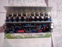
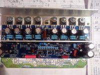
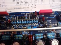
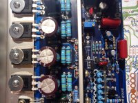
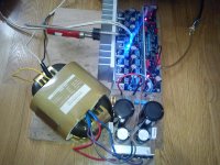
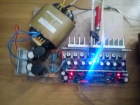
Finally I have something to show about 200W CFA VMOSFET.
I made big mistake populating first board, and I was to confident in my simulation and my layout. Nothing wrong with simulation, but I made to many layout errors, as missing connection, short connection and so on. It is not easy to trouble shoot electronic if there to many layout errors. I have found some but again my first board behaves strange and I was suspecting oscilation, but coud not see any with my scope.
Than I started second board and did it in small steps, first CCS only, than next some more connection, and then the VAS. That showed error and I found the layout error. Next where the drivers and again I found layout error. So I did it in steps and have found all layout errors.
It was thermally overcompensated and I added a blue LED between Vbe multipliers emitters and now the compensation was almost perfect, a bit overcompensate and that is good. From the room temperature up to 50 degree Celsius bias current drops less then 10%.
Not yet listening just bias setting and stability control, no oscillation.
It looks like the simulation was quite accurate thermally and electronically stability wise.
Time to repair the first board, I know now all layout errors, but during testing something happened, not sure what, and I have to find the what vent kaput. I hate desoldering from double sides PCB, metalized holes are killing me.
Here are some photos.
BR Damir
Attachments
Looking Extremely GOOD, hoping it will sing the same way. Excellent work. Very Professional.
Thank you Chris, you are to kind.
Damir
listening report-one channel
First I did some testing with +-50V power supply as that one is with the higher voltage I have and it showed good behavior with 8 ohm load. As I have only quite small heatsink I did not push it to far, but sinus and square waves were good(I have very simple signal generator home made).
Now came some listening with one channel only and without DC servo opamp in the socket. I have some problem with DC servo, it looks that it has some motor booting effects. DC offset with no opamp was about 100mV and that is not problem for my loudspeaker.
It is very quiet, I can't hear anything with may ear close to the loudspeaker, no turn on tump, and music is playing very nicely, all caps are new, power supply is new, unused yet. I am very satisfied with my first 30 minutes listening, as with that small heatsink it get quite hot, so I switched it off.
BR Damir
Attachments
First I did some testing with +-50V power supply as that one is with the higher voltage I have and it showed good behavior with 8 ohm load. As I have only quite small heatsink I did not push it to far, but sinus and square waves were good(I have very simple signal generator home made).
Now came some listening with one channel only and without DC servo opamp in the socket. I have some problem with DC servo, it looks that it has some motor booting effects. DC offset with no opamp was about 100mV and that is not problem for my loudspeaker.
It is very quiet, I can't hear anything with may ear close to the loudspeaker, no turn on tump, and music is playing very nicely, all caps are new, power supply is new, unused yet. I am very satisfied with my first 30 minutes listening, as with that small heatsink it get quite hot, so I switched it off.
BR Damir
😎
Way to go Damir, Slow and Sure. Just let me stop drooling over those beautiful Power transformers. I hope they make them big enough for my 400 watter as soon as you finish perfecting your design, which should be soon. Who is the manufacturing company for those.
Keep up the excellent work, and do not let the grand kids down, they have a great Grand Dad.
Keep up the excellent work, and do not let the grand kids down, they have a great Grand Dad.
Way to go Damir, Slow and Sure. Just let me stop drooling over those beautiful Power transformers. I hope they make them big enough for my 400 watter as soon as you finish perfecting your design, which should be soon. Who is the manufacturing company for those.
Keep up the excellent work, and do not let the grand kids down, they have a great Grand Dad.
Hi Chris, I am afraid I forgot what was the name of the shop where I bought the transformer, only remember it was French. Transformer on the photo is 500VA and not enough for two 200W channels and the voltage is only 2x36V AC, planed for my TT amp.
Cheers
Damir
I think that MAYBE 4 of these operating at 120 volts input might do the trick, what do you think?
Transformateur R-CORE à fixation sur châssis 500VA - 2 x 36V - R-CORE pour châssis
Separate plus and minus and channels...it sure would look impressive if nothing else...
Transformateur R-CORE à fixation sur châssis 500VA - 2 x 36V - R-CORE pour châssis
Separate plus and minus and channels...it sure would look impressive if nothing else...
- Home
- Amplifiers
- Solid State
- 200W MOSFET CFA amp