FS: Distinction PCB. Sale price is $1 plus cost postage world wide.
Shane
PCB has been sold.
Thank you for your interest.
Shane
Hi Guys,
Here attached is a parts guide to the Distinction PCB as promised.
These values are the ones i am currently using and are by no means the only values that can be used. For example if you decrease C1 to 260pF, you can decrease C3 caps to 330nF (rough estimate) and then use a 1206 sized cap.
C1 470pF
C2 1uF cornell dublier stacked film
C3 1uF cornell dublier stacked film in a 1210 package soldered on sideways (1206 footprint)
C4 and C5 (Two options -smd or through hole) are the analog output filter caps. At the moment ive just put in 4.7nF Vishay films and it seems to clean up the highs quite nicely.
C6 100uF Nichicon FP. But the ones Eldam suggested will be going in soon. (Panasonic LE caps)
C7 is a through hole option to C1. Or you can connect your own DEM circuit here.
R1 Carbon film 6k8. Those MELF resistors may be a good option here.
Hope this helps.
Attachments

For me it could be :
C1 : smt silvered MICA (John's input in him thread)
or if C7 instead: Wima radial FKP2 (in 5 mm pitch leg) or radial silvered mica (minimum voltage advised to avoid the largest pitch between legs the high voltages refs have !).
C2 : 3 choices : acrylic from Cornel Dublier or PPS (take care of the size, check the size on the datasheet) : 1 uf. Or 0603 case size, 0.1 uF ceramic class I: COG/NPO ( ceramic class 2 not advised); advised only in the goal for C6 decoupling. Or: empty.
Best to test C6 with C2 empty; then C2 with 1 uF and after C2 with 0.1 uF COG : take your time, check with listening with C6 already choosed. Not really advised to stack the 0.1 on the 1 uF if you have the idea to do it...
C6: depend on the PS : if shunt regs: 1 uF could be enough : Wima FKS2 : 2.5 mm pitch (seems to make the difference with the 5 mm pitch elswhere ?!) or discontinued OSCON SP (with higher capacitance values in this case !)
with linear regs : for the -/+ 5 V rails. One should try : discontinued Black Gate (47 uF minimum); OSCON SP (6.3 V >470 uf are the ones I prefer); Nichicon PLE (6.3 V /470 uF); UCC: polymer PSA serie: 470 uF (the smallest form: 470 uF) ; Panasonic: polymer SEP serie: 470 uF (not SEPC or SEPF !). IMHO from the best to the less best (depend on your hifi system and personal tastes).
Notice than the Nichicon PLE does not exist for the voltage higher than 6.3 V, so notr for the -15V rail !
R1 : MELF first ! (or, second choice) : Sussumu smd thin film resistor (RD low noise?)/ Vishays low noise... I have a doubt (but don't know!) about carbon because noise and precision ! No problem to pair/match exactly the same values for th etwo résistors. with smd MELF, smd Sussumu.
Could be funny also to putt those biggest cap on the AO vias (with a wire at each pins for outside connections), in this case the vias and smt pads have to be populated for decoupling : 1 uF MKS2 (2.5 mm pitch) or the acrylic/pps smd ! Why this strange idea... for a reason i don't understand (I'm not technician) when several boards and PS, putting a cap at the edge of the pcbs is advised (if someone could explain why or if I'm wrong: thanks in advance).
Or Whatever you like/prefer in relation to your system !
During chosing test : advised to avoid soldering for the radial capacitors (just take care to have shor legs enough to avoid shorts below the pcb ! always switch off before changing caps : Bah you know it already, but good to repeat it... TDA1541 chips are rare !).
For I2S inputs :
uf-l wires, no more than 10 cm (the less the best) as said in the "Any good TDA1541 kit enough" where this pcb was born !
or thin 50 ohms individual coax cables (shielding is the Gnd) if uf-l connectors are not choosed (but vias are very microscopics... so!).
I/V resistor : Through hole Rhopoint Econistor seems one of the best choice : Thorsten, John advice to it ! (less sterile than a TI Z foil) (sourcable at Rhopoint or Farnell easily) : value dépends on your design of course (your choice) !
Last edited:
Thanks to all that donated.
I've just counted up all the donations and have passed the money plus a bit extra from myself onto diyaudio.com.
So thanks to all that donated, im sure it will be appreciated and go towards helping a website that supports our hobby.
Ryan
I've just counted up all the donations and have passed the money plus a bit extra from myself onto diyaudio.com.
So thanks to all that donated, im sure it will be appreciated and go towards helping a website that supports our hobby.
Ryan
Please send me a PM if you have an extra board. I'm actually looking for 2, but 1 would work for now.
James
James
Please send me a PM if you have an extra board. I'm actually looking for 2, but 1 would work for now.
James
Hi James,
None in stock at the moment, but if you would like to wait for the next run, add yourself to the list.
Thanks for your interest.
Ryan
Just added myself to the list, but if someone has an extra board, I'm a buyer.
Also donated $10 to diyAudio, because I haven't lately.
James
Also donated $10 to diyAudio, because I haven't lately.
James
Strong endorsement!
If you are interested in getting the most out of the TDA1541a get your name on the list. I have my Distinction board running and the system burned in now for 300+ hours. Sound is in a different class to my former 1541a best effort. Nice job Ryanj.
If you are interested in getting the most out of the TDA1541a get your name on the list. I have my Distinction board running and the system burned in now for 300+ hours. Sound is in a different class to my former 1541a best effort. Nice job Ryanj.
Hi Wlowes,
did you solve yur little poblem of glitch ? Was it the Wave I/O or the nano player ?
Some prefer the non isolated side of the Wave I/O 🙂
BTW like this last with the Ian's simultaneous board !
did you solve yur little poblem of glitch ? Was it the Wave I/O or the nano player ?
Some prefer the non isolated side of the Wave I/O 🙂
BTW like this last with the Ian's simultaneous board !
Hi Wlowes,
did you solve yur little poblem of glitch ? Was it the Wave I/O or the nano player ?
Some prefer the non isolated side of the Wave I/O 🙂
BTW like this last with the Ian's simultaneous board !
Hi Eldam
I have not solved my glitch. (noise on 96k). It works very well at 44.1 which my current music collection, so i am enjoying taking it slow. I think it could be noise being picked up by usb cable but need to continue to rule out scenarios.
It sounds great. It is possible if I have some issues with noise on usb or i2s that there is even better sound ahead. Hard to imagine.
Did you try without the BBB ? I have posted a question in the PC section about FS speed and those little nano boards...
WHat happen if you use just the Wave I/O non isolated + uf-l to the Distinction core board ? Glitchs ? Same test with the isolated side ?
Some EMC of the traffos on the I2S wires ?
Have you a macro pictures of the BBB-WAVE I/O-Distinction chain links ?
WHat happen if you use just the Wave I/O non isolated + uf-l to the Distinction core board ? Glitchs ? Same test with the isolated side ?
Some EMC of the traffos on the I2S wires ?
Have you a macro pictures of the BBB-WAVE I/O-Distinction chain links ?
If you are interested in getting the most out of the TDA1541a get your name on the list. I have my Distinction board running and the system burned in now for 300+ hours. Sound is in a different class to my former 1541a best effort. Nice job Ryanj.
Thanks very much.🙂
I have very immersive experiences with my current setup. Ive been playing around with the XO lately and have had quite significant improvement in SQ by doing a few very basic things.
- Reduce mechanical vibrations to the XO as much as you can.
- Insulate the XO from any convection currents.
- Obviously a very low noise PS and a very low phase noise crystal is critical.
I think when finances allow i'd like to upgrade the XO... $$$
Walter, im glad to have helped you achieve something special. 🙂
Ryan
Some ground the metal can of the Xo at its feet ! And some other putt around it Blue Tack 
All those RF signals near multiple traffo may not help as well, a problem for all of us !
If Shane (Ceglar) woul be here yet (banned for not having respect a 7 days banning period and have laugh about teeths of SY picture avatar) : he would advise to go further :
- Ian's FIFO + reclocker board with Crysteq crystal ! Ian is now playing with OCXO and notice a serious improvement ! But don't know if he talk about a TDA1541 or an ES9018 DAC ! He has both and listen on BW 804 !
Hope Wlowes you tell us more about the analog tubes stage you set up... nos ref, setup, etc !
Ryan, I don't remember : is there in the bottom plane some plane ground ( but the analog Gnd one I mean) tied to the upper side digital ground ?
Analog Gnd just (only) tied to digital Gnd by the upper side of the pin 5 vias ?
Hi Eldam,
On the Distinction-1541 pcb, the digital and analog grounds are both connected to the top plane. Digital ground is also connected to the bottom plane.
Yeah im a bit annoyed Shane got banned... now even less conversation at diyaudio.
On the Distinction-1541 pcb, the digital and analog grounds are both connected to the top plane. Digital ground is also connected to the bottom plane.
Yeah im a bit annoyed Shane got banned... now even less conversation at diyaudio.
Hi Eldam,
On the Distinction-1541 pcb, the digital and analog grounds are both connected to the top plane. Digital ground is also connected to the bottom plane.
Yeah im a bit annoyed Shane got banned... now even less conversation at diyaudio.
Is it a permanent ban?
bummer, he was a good guy to have around. I don't recall him ever being troublesome.
Any way back to my led and jfet matching🙂
Any way back to my led and jfet matching🙂
Tube Output
Sorry for late reply..
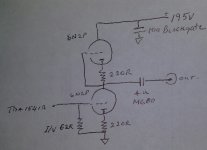
I have used Lampizator tube output now on several CD players and my previous DAC. This is just a cleaner build of the same using better parts and for first time his best PS. Below are pics of circuit diagram. I believe he credits the tube amplifier design, (he claims it is not a buffer) to his friend and mentor at ARG amplifiers(Ewgenniy Kreminsky).
I do not follow all his advice. I use an I/V resistor of 60R. Best quality here is high payback. I tried many different resistors and hand wound Manganin wire used here. Alternative would be Rhopoint.
For cathode resistors I used NOS AudioNote Tants. The whole thing is sounding good, but I am itching to hear it with more DIY Manganin. I have build the resistors and will install them asap.
The coupling cap is Russian MGBO-2 4u. It is great value. Clear upgrade would be Duelund RS.
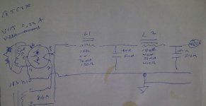
On PS, I use all Hammand iron for trans and chokes. Values are mentioned. I use separate trans for each channel and wire for 115v output. My B+ measures 195v. The film caps are 100u 400V polyprop caps used for solar panels. I like the convenient square shape. First caps after diode is 2u Obligato PIO I had left over. If I did it again I might build 2u, 50u then 100u.
The Diodes are Russian 5C3S.
The other important thing is star ground is close to tube output.
Hope Wlowes you tell us more about the analog tubes stage you set up... nos ref, setup, etc !
Sorry for late reply..
I have used Lampizator tube output now on several CD players and my previous DAC. This is just a cleaner build of the same using better parts and for first time his best PS. Below are pics of circuit diagram. I believe he credits the tube amplifier design, (he claims it is not a buffer) to his friend and mentor at ARG amplifiers(Ewgenniy Kreminsky).
I do not follow all his advice. I use an I/V resistor of 60R. Best quality here is high payback. I tried many different resistors and hand wound Manganin wire used here. Alternative would be Rhopoint.
For cathode resistors I used NOS AudioNote Tants. The whole thing is sounding good, but I am itching to hear it with more DIY Manganin. I have build the resistors and will install them asap.
The coupling cap is Russian MGBO-2 4u. It is great value. Clear upgrade would be Duelund RS.
On PS, I use all Hammand iron for trans and chokes. Values are mentioned. I use separate trans for each channel and wire for 115v output. My B+ measures 195v. The film caps are 100u 400V polyprop caps used for solar panels. I like the convenient square shape. First caps after diode is 2u Obligato PIO I had left over. If I did it again I might build 2u, 50u then 100u.
The Diodes are Russian 5C3S.
The other important thing is star ground is close to tube output.
Attachments
- Status
- Not open for further replies.
- Home
- Source & Line
- Digital Line Level
- Group buy/Interest list - TDA1541A Core board.