50pF/m to 150pF/m is common for signal interconnects.
5m of 150pF comes to 750pF
If an additional 470pF of RF attenuation is fitted at the Receiver, then the total will come to 1n22F
all the predictions use very simple arithmetic.
Similarly, the arithmetic for predicting the maximum output impedance of a passive vol pot is very simple.
Routmax = ¼{Rs+vol pot}
if your Rs is 50ohms and the vol pot is 10k then Max Rout is {10000+50}/4
Thank you, now it’s clear to me !
… I have to say that yesterday I’ve measured the inpedance of the pot just to be sure that all was OK and I’ve discovered that there was a short in the pot between the input and one resistor ! So right and left channels didn’t have the same impedance! I fixed the issue and now My-ref sing once again : )
Firstly, I didn’t suspect there was something wrong because, at the same time, I changed zeners and two caps on the PCB and also because the difference was very little but, yes, when I fixed the short on the pot the sound become more defined, less veiled.
Good 🙂
Anyway, I’ve tried to bypass the pot and listen using the remote control of the CD player. I’m not still sure, I’ve to listen more but maybe without pot the sound is a little bit more defined. Maybe there are more high frequencies. I will listen in the next day the real impact of my potentiometer on sound reproduction and take a decision about it. I do not need the pot because I have the remote control for the CD player and I have an external sound card with pot (EMU0404) for the PC, but I prefer to have a volume control on the amp because it’s more handy. I forget always where remote control is, on the sofa, on the table, in the kichen… and I don’t like to search for it for 10 minutes before listen music 😀
It is hard to say, after having bought 90 resistors to make a ladder pot, but I have to admit that without pot the sound is a little better. The stage is wider and the instruments are more defined. This is not a huge difference, it is just a nuance (I would say 1/5) but the improvement goes in the same direction as when I replaced LM318 with LF07.
Is it just a matter of high-frequencies attenuation? Does anyone could confirm this type of improvement bypassing the potentiometer?
Is it just a matter of high-frequencies attenuation? Does anyone could confirm this type of improvement bypassing the potentiometer?
The issue is more or less distortion I would think. This is why people like the Lightspeed. Resistor material also makes a difference.
It is hard to say, after having bought 90 resistors to make a ladder pot, but I have to admit that without pot the sound is a little better. The stage is wider and the instruments are more defined. This is not a huge difference, it is just a nuance (I would say 1/5) but the improvement goes in the same direction as when I replaced LM318 with LF07.
Is it just a matter of high-frequencies attenuation? Does anyone could confirm this type of improvement bypassing the potentiometer?
It depends on the resistors used in the stepped attenuator - I used a mix of Beyschlag and Taiyo Yuden mini-MELFs in a 6-step series-tapped (not R-2R) attenuator, and found an improvement over a stock carbon track pot, mainly in the reduction of glare. With good through-hole resistors, the improvement should be even more perceptible.
Dual-resistor 2-pole tapped attenuators should be even better, because the number of resistive elements is limited.
Thank you guys for yours advices 😉
I've used Takman metal film, I think they're good ones! I highlight that is a matter of nuance, I have listen accurately to hear the differences. I don’t know if am able to discern if it’s playing with pot in or without it, if just I turn on the amp when I wake up ! But when I’m listening and I switch between pot and no pot, yes there is a light difference, wider stage and more defined positions. Even if I doubt that is a good test, I’ve tried to use foobar equalization just to understand if it’s matter of high-frequencies cut off, I don’t think so because with +1db (8-20khz) the sound is more defined but harsher. When directly connect to CD player is just clearer.
Anyway, I like the way it sounds 🙂
I'm considering a bi-amp with 2 My-ref and reading many threads here in DIY and elsewhere, may I ask you just if this plot is right ? I need some gain to match speakers:
Attachments
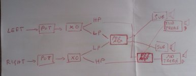
that does not look right.
Left >> vol pot >> HP filter >> power amp >> mid/treble
Right >> vol pot >> HP filter >> power amp >> mid/treble
That's your stereo channels.
For the bass only single channel ( the .1 of a 2.1)
Left >> input 1 of summing circuit
Right >> input 2 of summing circuit
output of summing circuit >> LP filter >> bass only Power Amp >> bass only speaker.
The summing circuit ADDS the two input signals to give double the VOLTAGE as an output.
You then filter that to remove mid and treble and you end up with double the voltage to feed into the bass only amplifier.
You should not need any extra gain. You are more likely to need some attenuation. For this attenuation I'll show a modified version of the above:
Left >> input 1 of summing circuit
Right >> input 2 of summing circuit
output of summing circuit >> LP filter >> lin law pot >> Buffer >> bass only Power Amp >> bass only speaker.
I'm sorry, I should say woofer and not sub. I prefer a stereo setup because the XO will be set between 180 and 220hz, LR IV.
In case, if it’s better, I can use a 4 channels potentiometer and shift it after the XO:
----------->HP>>POT>>PRE-AMP
IN>> XO>>
----------->LP>>POT>>PRE-AMP
How much is the input maximum voltage in My-ref ? I will need about 4-5db gain in the preamp for the woofer. I assume that I cannot use just one pre-amp for woofers only ...
Last edited:
Kreisky, your design has a potential for severe hum caused by ground loops. The signal grounds are split at the source (left and right) then split (high and low) and then rejoined at the pre-amps.
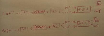
Bi-amp means two amplifiers.
Why is your diagram showing one amplifier in each channel?
In my diagram, AMP 1 and AMP 2 are two stereo amplifiers, one for each channel (left and right) to avoid ground loop as Mark said.
Of course, I would prefer to have the possibility to use one stereo amplifier for woofers, but this way I reintroduce ground loop, isn't it ?
Attachments

amp1 = two amplifiers.
OK.
I consider it better to use one stereo amplifier to drive one 2way speaker with very short speaker cables and a longer pair of interconnects coming from a conveniently located volume controller.
The alternative of having a centrally located stereo amplifier driving two similar drivers with long speaker cables is not as good in my opinion.
Last edited:
Look at your diagram.
The two Sources left and right will have a common signal return at their outputs.
Now look at the routes leading to the final power amplifiers. There are a return/grounds all the way through. If these get commoned again anywhere along those routes you will have a ground loop.
D.Joffe explains this and gives a solution.
Bi-amp means two amplifiers.
Why is your diagram showing one amplifier in each channel?
Typically that would be vertical bi-amping but it requires at least 2 channels on the amp. The Rev.C is a mono PCB. Do you have two PCB's per chassis?
Thank you Andrew, so you consider the vertical version of my design, the better. Also less problems with ground loop.amp1 = two amplifiers.
OK.
I consider it better to use one stereo amplifier to drive one 2way speaker with very short speaker cables and a longer pair of interconnects coming from a conveniently located volume controller.
The alternative of having a centrally located stereo amplifier driving two similar drivers with long speaker cables is not as good in my opinion.
Speakers are not very far from the central amplifier, 1,5 meter of interconnect, but I will consider to put the two stereo amplifiers near respective left and right speaker. The volume controller would be in the center before preamplifiers.
This with concern the horizontal version, with one stereo amplifier for both woofers and one stereo amplifier for both mid+tw.Look at your diagram.
The two Sources left and right will have a common signal return at their outputs.
Now look at the routes leading to the final power amplifiers. There are a return/grounds all the way through. If these get commoned again anywhere along those routes you will have a ground loop.
D.Joffe explains this and gives a solution.
I have read D. Joffe paper it’s a little bit difficult for me, but then I found your explication here 🙂. As you say “That resistor is between the Signal Return and the Power Ground. But look carefully at D.Joffe's diagram. Identify the Signal Circuit. The resistor is NOT in the route of the signal around the signal circuit.
The added resistor is in the LINK between the Signal Circuit and the Power Ground.”
In my diagram, AMP1 and AMP2 are both stereo amplifier, I have a stereo PCB of My-ref, this PCB was intended for A version but I have modified it into C version. So… yes, I have a stereo amplifier per chassis.Typically that would be vertical bi-amping but it requires at least 2 channels on the amp. The Rev.C is a mono PCB. Do you have two PCB's per chassis?
A shot of my stereo PCB is here.
Last edited:
The MyRef was designed with 1 Ohm resistors between the input grounds (AGND) and the power ground (GND).
Here they are shown as R9 and R50.
http://www.diyaudio.com/forums/chip-amps/54571-my-audiophile-lm3886-approach.html#post609507
Here they are shown as R9 and R50.
http://www.diyaudio.com/forums/chip-amps/54571-my-audiophile-lm3886-approach.html#post609507
Typically that would be vertical bi-amping but it requires at least 2 channels on the amp. The Rev.C is a mono PCB. Do you have two PCB's per chassis?
I don't know what he or you are calling a "vertical version"................. so you consider the vertical version of my design, the better. Also less problems with ground loop...................
I explained how the ground loop is created.
I told you who's paper discusses it.
Read Joffe again. Fig5 is the solution to the fig4 problem loop.
I don't know what he or you are calling a "vertical version".
I explained how the ground loop is created.
I told you who's paper discusses it.
Read Joffe again. Fig5 is the solution to the fig4 problem loop.
Thank you for informations you gave me !
I consider this one as a "vertical" bi-amp and if am not wrong, there is no ground loop here:
amp1 = two amplifiers.
OK.
I consider it better to use one stereo amplifier to drive one 2way speaker with very short speaker cables and a longer pair of interconnects coming from a conveniently located volume controller.
Do you think that 6db of gain in the preamp could be handled by My-ref without causing distortion ?
amp1 = two amplifiers.
OK.
I consider it better to use one stereo amplifier to drive one 2way speaker with very short speaker cables and a longer pair of interconnects coming from a conveniently located volume controller.
I just recently tried this setup and i fully agree, dont know why but i assumed for many years that having long speaker cables was better than having long interconnects. I now know better, never stop learning!
Ok Mark, this resistor seems to be (if I am not wrong) in the right place to break the ground loop so ... maybe not too much noise problem with My-ref design.The MyRef was designed with 1 Ohm resistors between the input grounds (AGND) and the power ground (GND).
Here they are shown as R9 and R50.
http://www.diyaudio.com/forums/chip-amps/54571-my-audiophile-lm3886-approach.html#post609507
I just recently tried this setup and i fully agree, dont know why but i assumed for many years that having long speaker cables was better than having long interconnects. I now know better, never stop learning!
Thank you Davym for sharing your experience, I will see step-by-step if I will be able to build this design. It will depend from speaker’s sensitivity, I have not yet bought woofers (I will take a 10"), and from watts needed. No to much watts actually, small room and low SPL.
I hope 40W will be enough but I know that 400W it’s better…
Now I have "only" to choose active XO and preamplifier, there are many XO designs and threads in DIY but they are maybe too difficult for me. I hope to find something with very good documentation and BOM, ... a PCB would be great to find, but I think there is no active XO PCB made from DIYer. Going on reading...
Now I stop, because I'm too far of topic ! If someone has some suggestion about active crossover, it will be nice to post it here 😀 That's an old thread that I opened 2 years ago before... giving up with this project 🙄
thanks again !!!
🙂
- Home
- Amplifiers
- Chip Amps
- The new "My Ref" Rev C thread