Can you get an Electromagnetic camera? Something like an Infra-red camera. You would be able to see how the emission increases around the untwisted wires as the current increases.
Many builders of the "Ultimate BOM," including me, used large input caps off the board. As much as I can remember, no one took extraordinary precautions about twisting the pair of leads, and all the amps ran quietly. This is too much excitement about what is most likely an unimportant issue. It's best to put at least one lead of the cap directly into its pad on the PCB, with the other end soldered to the input lead (or even the RCA jack itself, if it will reach), and keep the cap as close as possible to the board. Two inches may be too far away. The negative pole input lead can go directly to its proper place on the pcb. Chances are very good there will not be significant interference or noise. If there is, then you will need to refine your wiring. Until then, don't worry about it.
In fact, I would say it's more important to secure the input cap against a solid surface to reduce vibration as much as possible than it is to obsess over an inch or two of untwisted lead wire.
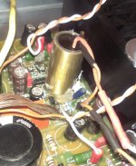
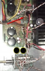
Here are bad pics of very good amps that ran perfectly silent with off-board caps and untwisted input leads.
Peace,
Tom E
It's what I was about to do, actually.
Let's see what other smaller caps I will decide to use. Otherwise for the Obbligatos This is the only way. Glad to know it is not impossible the solution works well.
Btw, I have some Obbligato Platinum in 1uF size, that is about half of the one of the 2.2 and would probably fit or be very much close to the board. Any complaint using 1uF..?
Last edited:
I do not understand the reason for your suggestion.
First, how much current flows through a pair of amplifier input wires?
Second, why would one care if the wire EMITS anything? We are concerned with induced hum and noise.
Last, why go through any extra trouble for two or fewer inches of input wire? If the cap is close to the board, as I suggested, there will be a very short bit of input lead that is not twisted pair. If that picks up noise, one should be able to hear it. If one can't hear it, then who cares?
This should not be an important issue with this amplifier, especially if it is inside a metal enclosure.
Peace,
Tom E
No, but those transformer leads are emitting (increasing with the amount of current) and the input leads are receiving.
I go back to my question: what about the use of the Obbligato in 1uF specs? Can someone report of a bad about the 1uF instead of the 2.2uF?
Thanks.
Thanks.
Yes, you can use the 1 uF input capacitor. There are some who find it to sound a bit thin at the low-end compared to a 1.8 or 2.2uF, but YMMV. I've used everything from 1 uF to 4.7uF without much bother.
Yes, you can use the 1 uF input capacitor. There are some who find it to sound a bit thin at the low-end compared to a 1.8 or 2.2uF, but YMMV. I've used everything from 1 uF to 4.7uF without much bother.
Great, thanks!
Hi all, I skimmed through this thread but I cannot find any reference to a seller of a MyRefC kit. How are these kits brought to the public ? Thank's
There have been a variety of Group Buys.
There may be some of the FE version left over for sale.
There may be some of the FE version left over for sale.
Hi all, I skimmed through this thread but I cannot find any reference to a seller of a MyRefC kit. How are these kits brought to the public ? Thank's
I do still have some MyRef Rev C kits left, with both Standard and Premium parts. The board layout is mine, and is broadly similar to the Twisted Pear v1.2 boards, but with more component flexibility as well as the ability to mount larger components at many locations. Some bypass caps have been omitted, and a couple of additional ones added. PM me or email me at siva dot chander at gmail dot com for further details.
Hi all, I skimmed through this thread but I cannot find any reference to a seller of a MyRefC kit. How are these kits brought to the public ? Thank's
@ r100 and others who may want to avoid the build process - I believe Siva still sells the V1.3 boards/kits, but I'm planning to sell several of my completed projects over the next few weeks
 . They include a V 1.2 (red boards), a V 1.3 w/LF01 modules and a FE RC build. They all are fully functional and sound great. The RC set is in the chassis I shipped around and can be included if desired. PM me if interested and I'll supply details and pictures.
BTW: Other items so sell:
Brian GT Monoblocks w/Resistor Replacer Mods
Lightspeed Attenuator
Lighter Note LDR Attenuator build
JC-2 Preamp (Completed/tested board only)
Several pair of input caps.
Last edited:
Hello !
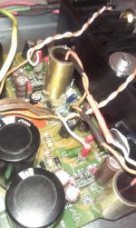
I'm trying to end my My-ref C but I have a problem with Obbligato cap, they're to big. So I've placed one of them on a wood socket + glue, but it becames to hot. After 2 hours playing there is quite a heat difference between the two capacitors 🙁 One is warm, the other is to hot.
One way would be trying to use something different from wood+thermic glue, maybe a glass tube would better dissipate heat.
The second way is to place both caps between pot and PCB, in a little separate PCB. But I don't know if it a good idea 😕
Or what else ???
thank you for your help !
marco
Attachments
Last edited:
A signal capacitor should never become hot, not even warm.
The power dissipation in a signal capacitor is below micro watts (<µW)
The power dissipation in a signal capacitor is below micro watts (<µW)
A signal capacitor should never become hot, not even warm.
The power dissipation in a signal capacitor is below micro watts (<µW)
... of course you are right 🙂
So maybe it depends from the heat coming from other components and radiator ?
The cap in the right, the colder one, is more distant from others components, maybe this is the cause of different heating. I don't know...
The amp works well.
Ok, no issue with cap heat, it works 😉
Anyway I would to ask you, very skillful electronic people 🙂, if a buffer will enhance or not My-ref C musical reproduction?
This is my setup:
CD player impedance output (50ohm), 2V
Pot stepped stereo Ladder 12k
My-ref C
To be honest, for enhance substantially my setup I should biamplificate my speakers (DIY Peerless two way, bass-reflex, 85db). I like My-ref sound but I think it lacks a little bit of "energy" and "live" feeling driving my speakers, I think that an active filter should improve this. I've read the B1 active crossover thread but it's too difficult for me 😱. I have not such skill, I can just solder and assemble PCB but I am not able to calculate active filter and different slopes for baffle step etc...
So I was wondering if any buffer would improve in the same direction the sound of my setup... something like Salas DCB1 or Kuartlotlon...
Thank you for your advise!
You have a question to ask yourself:
Can your 12k attenuator drive the interconnect and the Receiving amplifier effectively?
If yes, then you do not need and cannot benefit from an added Buffer.
If no, then you need a Buffer on the output of the attenuator.
You do not need a Buffer on the input of the amplifier, there is no benefit to be gained, except in one rare operation.
If your amplifier is an inverting arrangement and/or has a very low input impedance then a Buffer that isolates the inverting input from what you can do is an advantage. eg disconnecting the interconnect of an inverting amplifier can cause the power amp to oscillate and destroy speakers.
You have a question to ask yourself:
Can your 12k attenuator drive the interconnect and the Receiving amplifier effectively?
If yes, then you do not need and cannot benefit from an added Buffer.
If no, then you need a Buffer on the output of the attenuator.
You do not need a Buffer on the input of the amplifier, there is no benefit to be gained, except in one rare operation.
If your amplifier is an inverting arrangement and/or has a very low input impedance then a Buffer that isolates the inverting input from what you can do is an advantage. eg disconnecting the interconnect of an inverting amplifier can cause the power amp to oscillate and destroy speakers.
Thank you Andrew,
I've googled around and find that 1/10 ratio between source output impedance and input amplifier impedance is good enough...
If this is true, by using 12k ladder pot I have a ratio of 1/8, My-ref should have 100kohm input impedance. The pot is also near the PCB, so I argue that... maybe I have no benefits or too little one from using a buffer. Am I wrong ?
Last edited:
You should allow for capacitance, not just resistance.
Can a 12k attenuator that will have a maximum output impedance of ~3kohms, drive XXXpF of cable capacitance in parallel with 100k of resistive load impedance in parallel with XXXpF of RF attenuation at the amp input?
You are missing 2parts of the loading by just considering the 100k for Rin.
You could have 1n to 2nF of capacitance
F-3dB = 1/2/pi/R/C = 1/{2*3.14*3000*2}*10^9 = 26.5kHz
Your response at 26.5kHz is down by ~3dB when you set your 12k attenuator to -6dB and feed into 2nF of capacitance.
Most aim for ten times that limit ! I do.
To be honest... I’m not sure to understand but you seem to affirme that I don’t need buffer even if we consider capacitance.
About the pot I was wrong it's 10k ohm 😱
The circuit is that one : Stepped Attenuator Resistor String Calculator - Neville Roberts
Rx is almost from 10k to 7k, and Ry is from 0 to 3k. You assume a maximum output impedance of 3kohm, I do not know how to calculate this value, but if I use Rx values, the F-3db is in audible band.
The pot is in the same case and close to amp input, so the interconnect’s capacitance is quite small but I don’t know if it is less or more than 2nf.
Since I have an internal attenuator on the CD player (with remote control), if bypass the ladder pot and listen with cables directly connected from CD to amp input, could I listen if a buffer stage would improve sound reproduction ?
As I sais output CD impedance is 50ohm, so it's very good, but in that case the capacitance of interconnects is bigger because signal cables are 1 meter and I think with quite high capacitance...
Sorry if my questions are imprecise... !
50pF/m to 150pF/m is common for signal interconnects.
5m of 150pF comes to 750pF
If an additional 470pF of RF attenuation is fitted at the Receiver, then the total will come to 1n22F
all the predictions use very simple arithmetic.
Similarly, the arithmetic for predicting the maximum output impedance of a passive vol pot is very simple.
Routmax = ¼{Rs+vol pot}
if your Rs is 50ohms and the vol pot is 10k then Max Rout is {10000+50}/4
- Home
- Amplifiers
- Chip Amps
- The new "My Ref" Rev C thread