Home made is good !!
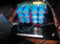
When everything fits !
The 82Kuf cap bank went well - looks pro and did not kill me. (below 1).
5 seconds soft-start timing from the controller is plenty for these caps.
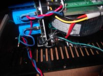
Had to redo my main star (below 2) to make the caps servicable , all the AC/earths
are to one side , allowing me to "swing out" the AC/ relay panel ..
Read this ... Earthing (Grounding) Your Hi-Fi - Tricks and Techniques For a DEADLY power supply
such as this , I will add the "high current safety loop" to the AC panel.
The amps run nice on the 73V rails ... no "unaccounted currents" , no noise/hum.
Tomorrow I will hear 250W Kypton C's and spooky's 🙂🙂 .
OS
When everything fits !
The 82Kuf cap bank went well - looks pro and did not kill me. (below 1).
5 seconds soft-start timing from the controller is plenty for these caps.
Had to redo my main star (below 2) to make the caps servicable , all the AC/earths
are to one side , allowing me to "swing out" the AC/ relay panel ..
Read this ... Earthing (Grounding) Your Hi-Fi - Tricks and Techniques For a DEADLY power supply
such as this , I will add the "high current safety loop" to the AC panel.
The amps run nice on the 73V rails ... no "unaccounted currents" , no noise/hum.
Tomorrow I will hear 250W Kypton C's and spooky's 🙂🙂 .
OS
Attachments
When everything fits !
The 82Kuf cap bank went well - looks pro and did not kill me. (below 1).
5 seconds soft-start timing from the controller is plenty for these caps.
Had to redo my main star (below 2) to make the caps servicable , all the AC/earths
are to one side , allowing me to "swing out" the AC/ relay panel ..
Read this ... Earthing (Grounding) Your Hi-Fi - Tricks and Techniques For a DEADLY power supply
such as this , I will add the "high current safety loop" to the AC panel.
The amps run nice on the 73V rails ... no "unaccounted currents" , no noise/hum.
Tomorrow I will hear 250W Kypton C's and spooky's 🙂🙂 .
OS
Do you think loop breakers are necessary on the earth ground or is the lifted ground on the signal input all that is needed?
It sounds like we think alike on not bringing speaker return noise back to the amplifier board. How do you route the speaker return wire? Andrew T keeps about repeating the twisted speaker leads. Should they be twisted back to the amp board, and then the speaker return be twisted in with the power rail leads back to the supply?
A.Do you think loop breakers are necessary on the earth ground or is the lifted ground on the signal input all that is needed?
B.It sounds like we think alike on not bringing speaker return noise back to the amplifier board.
C. How do you route the speaker return wire? Andrew T keeps about repeating the twisted speaker leads. Should they be twisted back to the amp board, and then the speaker return be twisted in with the power rail leads back to the supply?
A. I just implemented it . I was already silent , now I'm silent with a loop breaker 😀.Cordell uses one on his preamps ,
Rod elliot describes his - I picked Elliot's because it parallels all the bridge diodes (2- 70A diodes) and only has a .6V
"break point" (like the input circuit).
I added the 10R + a .1uf across the breaker (RF attenuator).
B. Driving my load with the speaker ground back to the OPS gave .2V ripple at
G1. back to the main chassis earth only <.1V - silent either way .... but why
"sour the milk" for G2 ?
C. Yes ... twisted all the way. I have the speaker return twisted with the OP
back to where it goes to the main star. I can't where it goes to the protection
board. I have the OPS G1 braided (twisted) with the 2 rails from caps to
PCB.
All this , I also see on 2 logitech sub wirings (AC and rails/ground) If the OEM's
also do it ... Cordell , Elliot , and Andy T. must be correct. 🙂
OS
Last edited:
A. I just implemented it . I was already silent , now I'm silent with a loop breaker 😀.Cordell uses one on his preamps ,
Rod elliot describes his - I picked Elliot's because it parallels all the bridge diodes (2- 70A diodes) and only has a .6V
"break point" (like the input circuit).
I added the 10R + a .1uf across the breaker (RF attenuator).
B. Driving my load with the speaker ground back to the OPS gave .2V ripple at
G1. back to the main chassis earth only <.1V - silent either way .... but why
"sour the milk" for G2 ?
C. Yes ... twisted all the way. I have the speaker return twisted with the OP
back to where it goes to the main star. I can't where it goes to the protection
board. I have the OPS G1 braided (twisted) with the 2 rails from caps to
PCB.
All this , I also see on 2 logitech sub wirings (AC and rails/ground) If the OEM's
also do it ... Cordell , Elliot , and Andy T. must be correct. 🙂
OS
Thanks. Hopefully all my instability issues are going to be gone with driver and output changes. I need to get the final layout design finished now.
Thanks. Hopefully all my instability issues are going to be gone with driver and output changes. I need to get the final layout design finished now.
Your instability really puzzles me ?? These amps were the most resilient of all.
I shorted things , forgot to attach things ( I was "rusty" 😱 ).
But , all 4 amps and 6 IPS's still work ?? A miracle !! 😀
Oh , ground the OPS heatsinks to main chassis star ... as well.
(especially on an anodized extrusion) .
OS
I probably test things a little too vigorously. Running the amp into a 4 ohm load until I can burn myself on the heatsink probably isn't a good idea. Every electronic product I design at work pretty much gets tortured to death before I put it to work. The fellow I work for is electronically challenged so I need to make everything so he can't hurt himself or burn anything by doing something stupid. I build tester prototypes for everything and if it survives I build a finished product.
I didn't catch anything on the scope but I think I was still possibly having a little problem at high frequency. The protection board shut it down on me around 100KHz a couple times after changing pre-drivers. I'll see what happens with faster drivers and outputs.
Last edited:
A small tip you Can connect a lightbuilb in serie with the powercord, and using a variable safety transformer -Nice to have when you turn on amplifier first time if the amplifier pulls a lot of current the lightbuilb Will just light until bias are adjusted Down or short circuit removed🙂
OS do you have any links to info regarding amplifier grounding?
Earthing (Grounding) Your Hi-Fi - Tricks and Techniques
Best i've seen.
OS
I'm going to assemble a set of output boards with 3 A1295/C3264 output devices. Will I be causing new issues installing 100uF for C116-123? Can C125 and C 127 be 1000uF? If I omit the cap multipliers would there be any advantage to increasing C103 and C106?
When everything fits !
The 82Kuf cap bank went well - looks pro and did not kill me. (below 1).
5 seconds soft-start timing from the controller is plenty for these caps.
The amps run nice on the 73V rails ... no "unaccounted currents" , no noise/hum.
Tomorrow I will hear 250W Kypton C's and spooky's 🙂🙂 .
OS
Update/catchup time --- where do i find the schematic for the latest version being built?
THx-RNMarsh
It was me, in cooperation with Jason Kuetemann, while you were "away" for some time 🙂
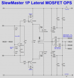
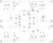
Gabor, I only use this design (very successfully) with IRFP240/9240 Hex-FETs. Never tried any other FETS here. However, I believe Toshiba's verticals will work fine. Please note - we had to modify the Vbe spreader (adding a red LED) for better match the tempco of IRFPs - this will most likely be required for Toshiba as well (see attached, plus my and Jason's posts earlier in this thread).
Thank you vzaichenk
To make myself clear I have some (20+ pair)Toshiba 2SK1529 & 2SJ200 so I would love to use them these in type of power stage.
I built several mosfet amplifier with lateral mosfet from Hitachi-Renesans and Exicon.
To me laterals has a bit soft sound (that would be not a problem at all) but a bit shy in bass region.
I read same report from other DIY-ers even do a lot of great amplifier was built with laterals.
Based on my research Toshiba has better bass in a similar circuit.
I know a lot of people use the IRFP type mosfet similar to Toshiba (I did to some Pass DIY project) but those are not audio semis.
Again I have 20+ pair of these Toshiba.
Two circuit was posted on these forum I do like them a lot one with IFPP hex-fet but that was not tested or built based on my research
The other was tested and perform very well but that was built with Lat-fet.
I would prefer to mode the Lat-fet version since that was tested but need some help to do so.
Also these circuit has the layout which would be easier to convert to Toshiba mosfet
Probably to much to ask but who knows if I newer try.🙂
Greetings Gabor
Attachments
Protection etc.
I've just finished reading the whole thread from the beginning. Feels almost like a book if you read it in few days.
Thanks OS and all who contributed, very nice development.
To those who actually built the amp: what did you finally use as protection board? Was it Valery's Arduino based solution?
Thanks a lot
Stefan
Thank you vzaichenk
To make myself clear I have some (20+ pair)Toshiba 2SK1529 & 2SJ200 so I would love to use them these in type of power stage.
I built several mosfet amplifier with lateral mosfet from Hitachi-Renesans and Exicon.
To me laterals has a bit soft sound (that would be not a problem at all) but a bit shy in bass region.
I read same report from other DIY-ers even do a lot of great amplifier was built with laterals.
Based on my research Toshiba has better bass in a similar circuit.
I know a lot of people use the IRFP type mosfet similar to Toshiba (I did to some Pass DIY project) but those are not audio semis.
Again I have 20+ pair of these Toshiba.
Two circuit was posted on these forum I do like them a lot one with IFPP hex-fet but that was not tested or built based on my research
The other was tested and perform very well but that was built with Lat-fet.
I would prefer to mode the Lat-fet version since that was tested but need some help to do so.
Also these circuit has the layout which would be easier to convert to Toshiba mosfet
Probably to much to ask but who knows if I newer try.🙂
Greetings Gabor
Valery came up with the idea to used VFETS. He and I both built them. They work very well. I also had an idea to build a small LFET board which Jason did a layout for and we built that one too. Jason sold boards for that so I am pretty sure there have been more built. Then Valery designed the TuBuSumo. That OPS has two pair LFETs and works very well though is designed to work with a higher current IPS than the Slewmaster IPS. It will work with them though because I have built and tried it.
Attachments

Update/catchup time --- where do i find the schematic for the latest version being built?
THx-RNMarsh
Yes , page 1 is what I have now ....
-the 5 pair "slewmonster" EF3 OPS
- and my choice of the "spooky amp" (VFA) , Kypton C (CFA w/servo+ baxandall VAS) , and Wolverine "blameless/LIN" CCS based VFA's.
All the above I have tested in the "real world" with my 57000 song collection - WOW !
FULL power ... quite impressive !
All works well .... except - my output stage is not centered on my extrusions.
This does not harm it , but one end of the OP heatsink is hotter than the other.
this summer it might present a problem as the T co-efficient widens as the
heat increases.
Still a few refinements to work out 😱 .
OS
Hi OS,
I would like to know about your KYPTON-C sound likes.
Talk about it.
( Triode sound? 😀 )
What´s your "review" ?
I would like to know about your KYPTON-C sound likes.
Talk about it.
( Triode sound? 😀 )
What´s your "review" ?
Last edited:
Hi OS,
I would like to know about your KYPTON-C sound likes.
Talk about it.
( Triode sound? 😀 )
What´s your "review" ?
Sounds like the spooky at normal volumes.. It has a strange "expansive" nature
at high volumes that the spook does not have.
But the spook has slightly more convincing bass. I nearly predicted this with
the simulator plus speculation on current FB/slew.
Actually , better than any amp I have heard (HK680/990/ genesis/ first badger).
Edit - the "spooky" on this OPS is nearly a clone of the HK990 - sounds identical - impressive/
With the 5 pair OPS and that huge power supply , ripple/PSRR is quite
minimized. The spook or wolverine VFA would most likely sound better on a
"challenged" PS.
With a smaller PS and the Kypton-C , I would go for a small dual mono
(300VA 20Kuf - per channel).
I'm even running the Kypton C without it's servo. But, that should make no difference.
I've never owned a Valve amp , but the clip of the kypton is similar.
(I can't compare what I've never heard) 😱
OS
Last edited:
Revelation -
VFA - isolated at low frequencies from the woofer (just voltage feedback).
Bass "goes on" as it wants to ... "better bass" ??
X-over "glitch" is sometimes faster than the feedback can compensate for.
Optimal (13-22mv/60-100ma) OP bias is crucial to SQ.
CFA- Back EMF and any other speaker property is "seen" right at a
low Z feedback node on the input stage.
X-over glitch can easily be negated by the speed of this type input stage.
A CFA on this EF3 is as good as a "super A".
OP bias can be almost to class B (0) before SQ degrades (wild , huh !) 😱
My reservations about the original "VSSA" are gone ... as the Kypton-C solves
any over current/saturation issues and has "acceptable" PSSR.
Ultimately , with my sub handling the bass .... Kypton-C might be my permanent choice.
OS
- Home
- Amplifiers
- Solid State
- Slewmaster - CFA vs. VFA "Rumble"