Tb46,
I think your drawings are fully awesome, thank you for taking the time to make those happen, i apologize for the constant revising .... Do you suppose we could crank out one more from you once we have a final revision? 😀
I may experiment with that idea of turning it by 90 degrees ...
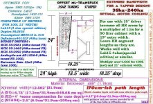
Here is my updated sketch for the 24" version, i put more work into trying to make everything match the HR sim more closely (S2 has to be fudged somewhat due to the depth of driver's cone, so that panel doesn't need quite as much angle as initially thought) ..
Things are color coded as follows:
- Black= External dimensions
- Fuscia= Internal Dimensions
- Aqua Blue= List of compatible 12" Drivers
- Green= Exciting scale-up data! (can be scaled up by making wider for use with 15s! Maybe even 18s! (but the 18s would have to be really "shoehorned" in because of the vertical constraints)
- Orange= Your cool optional path extension modification.
- Red= Notes and Info
I tried modeling the mouth chamber as an exponential flare at S5 but oddly enough adding the extra 23cm of path length (depth of the mouth) at such an extreme flare rate and nearly 1000 sq cm area at S5 (actually a bit less than that because the driver basket & magnet takes up some of that space) somehow managed to shift the FB upwards slightly ??? Which seems entirely counter-intuitive to me, if anything it should have been a downward shift by a hertz or two, because the path is extended by the mouth as it is in series (actually it does double duty because it is a series and parallel "shared" chamber, very Karlsonesque) ........ So anyway, i will just chalk this up to an HR quirk .......... After all when you place a cornerhorn tightly into a corner it doesn't shift the FB upwards, does it? Nevertheless this is "splitting hairs" at this point ..

I am enthused about the fact that a 15" driver fits so well in this sort of layout if it is made a few inches wider, the 4 ohm Lab15 special models well in the 90 liter version , 100 liters would probably be just about right for that driver in this design .... That is 50 liters less than my other (less offset) design for that same driver! 😀
Any thoughts ?
MMJ - I haven't started the build of the larger (150 liter) version of the box yet - should I hold off and consider a 100 liter version ......?
Hi MMJ,
Post #919: "...S2 has to be fudged somewhat due to the depth of driver's cone..."
I would disregard the throat volume (volume in the driver cone and the cutout). When you simulate a throat chamber (e.g.: Vtc=3000 Atc=700 Ap=S2 Lpt=1.2) it does not really change the outcome of the simulation.
Post #919: "...tried modeling the mouth chamber as an exponential flare at S5...somehow managed to shift the FB upwards slightly..."
Just tried it again in your 170 path length simulation from Post #914. Adding 15 cm L45 shifts the minimum in the displacement from 36.75Hz to about 33.72Hz, then increasing S5 from 220 to 1000 moves the frequency up to ~36Hz. So the added length does reduce the frequency, but the excessively rapid flare rate to the increased S5 actually looses path length. That kind of goes hand in hand w/ gaining a little bit of bottom end by reducing S5 in some TH (e.g.: the Keystone).
Right now I have to climb up into the roof crawl space to find out why there is water dripping (very little so far) from the light fixtures in the bathroom ceiling. If it aint' on thing, it's another. 🙂
Regards,
Wow thank you!!!
I am thankful to the group here on this website, what a great resource! =D
MMJ - I haven't started the build of the larger (150 liter) version of the box yet - should I hold off and consider a 100 liter version ......?
Beau ,
You would sacrifice about 2db of output at 35hz and 40hz with the smaller box at same input, but if you plan take these out for shows and parties they are certainly more portable than the 150 liter version ...
The offset box also has better upper bandwidth so you could reduce the stress on your tops by crossing over to them at a higher frequency ...
So you have optional compromises as always 🙂
I hope to be as useful in the futureI am thankful to the group here on this website, what a great resource! =D
Beau ,
You would sacrifice about 2db of output at 35hz and 40hz with the smaller box at same input, but if you plan take these out for shows and parties they are certainly more portable than the 150 liter version ...
The offset box also has better upper bandwidth so you could reduce the stress on your tops by crossing over to them at a higher frequency ...
So you have optional compromises as always 🙂
Beau ,
To be more precise it is about 1.5db loss at 40hz and 2db loss at 35hz (comparing the offset 100 liter cab to the less offset 150 liter cab for the Lab 15 special edition)
Observations
Oh gosh, be careful up there ... Crawl spaces can be so precarious, and water damage is crummy...
Good to know that the throat volume doesn't really change things noticeably🙂 ..... I am just curious about being able to straighten up that internal panel in a "stepped" version of the cab, i tried simming it and it looks good so far, using this arrangment would allow us to move the baffle back a little making the mouth chamber deeper (and the small folds above to be a little longer) squeezing out a combined increase in path length by around 5.8cm-ish at best..... hmmm ......
And yes, you are right , flaring (or adding more flare) to the end of an existing path should shift the FB upward, and it does exactly that, but I was seeing something else very strange in the model that was a little bit confounding to me .... I could add an additional 20cm (approximate depth of mouth chamber) to the existing path and because of the greatly increased area in the added 20cm section there was an upward shift in FB (in TH mode) , which is what i thought was odd .... Leaving the original path as it was and adding 20cm (even though it has a vastly larger area) going from 163cm + or - path to a 183cm path should have shifted the FB down (even by just a small amount) but instead shows a marginal upward shift ... Odd ...........
.NOW CHECK THIS PART OUT , trying this same thing in a different Hornresponse mode like OD mode , or ND mode shows a miniscule downward shift much more like i would expect and had a totally unanticipated benefit of helping to fill in the dip between the 5th and 7th harmonic (with a slight gain in midband response between 100hz and 200hz!! COOL !! Dip between 5th and 7th is still there but not as deep and not as wide ..... Would be awesome to be able to use these out to the 7th harmonic, thats past 300hz in this case, highly optimistic but possible, that would be some extraordinary bandwidth for a bandpass box! 😛 Real-world measurements would of course let us know what our honest usable bandwidth truly is .... I am looking forward to measurements of a real box when someone builds one.
Not sure what to think of the mode discrepancy , maybe David can fill us in on that.
Hi MMJ,
Post #919: "...S2 has to be fudged somewhat due to the depth of driver's cone..."
I would disregard the throat volume (volume in the driver cone and the cutout). When you simulate a throat chamber (e.g.: Vtc=3000 Atc=700 Ap=S2 Lpt=1.2) it does not really change the outcome of the simulation.
Post #919: "...tried modeling the mouth chamber as an exponential flare at S5...somehow managed to shift the FB upwards slightly..."
Just tried it again in your 170 path length simulation from Post #914. Adding 15 cm L45 shifts the minimum in the displacement from 36.75Hz to about 33.72Hz, then increasing S5 from 220 to 1000 moves the frequency up to ~36Hz. So the added length does reduce the frequency, but the excessively rapid flare rate to the increased S5 actually looses path length. That kind of goes hand in hand w/ gaining a little bit of bottom end by reducing S5 in some TH (e.g.: the Keystone).
Right now I have to climb up into the roof crawl space to find out why there is water dripping (very little so far) from the light fixtures in the bathroom ceiling. If it aint' on thing, it's another. 🙂
Regards,
Oh gosh, be careful up there ... Crawl spaces can be so precarious, and water damage is crummy...
Good to know that the throat volume doesn't really change things noticeably🙂 ..... I am just curious about being able to straighten up that internal panel in a "stepped" version of the cab, i tried simming it and it looks good so far, using this arrangment would allow us to move the baffle back a little making the mouth chamber deeper (and the small folds above to be a little longer) squeezing out a combined increase in path length by around 5.8cm-ish at best..... hmmm ......
And yes, you are right , flaring (or adding more flare) to the end of an existing path should shift the FB upward, and it does exactly that, but I was seeing something else very strange in the model that was a little bit confounding to me .... I could add an additional 20cm (approximate depth of mouth chamber) to the existing path and because of the greatly increased area in the added 20cm section there was an upward shift in FB (in TH mode) , which is what i thought was odd .... Leaving the original path as it was and adding 20cm (even though it has a vastly larger area) going from 163cm + or - path to a 183cm path should have shifted the FB down (even by just a small amount) but instead shows a marginal upward shift ... Odd ...........
.NOW CHECK THIS PART OUT , trying this same thing in a different Hornresponse mode like OD mode , or ND mode shows a miniscule downward shift much more like i would expect and had a totally unanticipated benefit of helping to fill in the dip between the 5th and 7th harmonic (with a slight gain in midband response between 100hz and 200hz!! COOL !! Dip between 5th and 7th is still there but not as deep and not as wide ..... Would be awesome to be able to use these out to the 7th harmonic, thats past 300hz in this case, highly optimistic but possible, that would be some extraordinary bandwidth for a bandpass box! 😛 Real-world measurements would of course let us know what our honest usable bandwidth truly is .... I am looking forward to measurements of a real box when someone builds one.
Not sure what to think of the mode discrepancy , maybe David can fill us in on that.
Last edited:
Beau ,
To be more precise it is about 1.5db loss at 40hz and 2db loss at 35hz (comparing the offset 100 liter cab to the less offset 150 liter cab for the Lab 15 special edition)
I think I'll try the smaller cab - of course that will mean I'll need to PM you a few more times (sorry).
Hello MMJ and all!
Looking back to the HR export named D12-ODMLTRV2 for the SWS-12D2, It looks like an awesome response! 100Hz is only 1.5dB down from the max of nearly 121dB!!! and 120dB is maintained from 40-60Hz with the 33Hz only -3dB from peak SPL! is this too good to be true? 🙁 The box seemed to be the same 22 x 18.25 x 14.5 outer dims as the later versions. What changes the response of the later models?
The SWS-12D2 (would allow me to run at 4Ohm on my GX5) and the LAB12 only have a 0.02" different bolt circle, I think I'll split the difference between the 2 and use T-Nuts to allow a swap for when I want to grab the Alpine driver 🙂
Last edited:
I think I'll try the smaller cab - of course that will mean I'll need to PM you a few more times (sorry).
Beau ,
Thats no problem at all, i am still just working out the last of the details on the smaller cab, almost done ..🙂
Apparently 24" is best for 35hz tune , 22" height could be great for 40hz tune
Sounds great! Good to know that those two drivers have such a similar bolt circle.
Palsa,
Both TB46 and I fiddled with the 22" height idea for a bit and we both came to the same conclusion that it just doesn't fit well, things just dont fall into place properly enough for a for a solid 35hz tune, and i know i wasn't feeling confident enough with the results so i ditched the idea , HOWEVER that 22" version would work very well with a 40hz tuning (by opening up the last few folds by a small amount) ....
24" height seems to be the ticket for a 35hz tuned box using this layout so i have gone back to modeling for those dimensions (24" x 13.5" x 18.25") with the extra 10cm or so of path length that it provides us ... This height also allows us enough room for the "Z" modification if needed OR also gives us the space to use a 15" woofer if we scale up the width of the cab ...
So my conclusion is that using the 24" height with the 35hz tune just makes more sense because not only does everything fit properly but it is also more adaptable and flexible...
The small increase in output in that sim may have been due to the somewhat shorter path and a few less centimeters worth of offset which can lift up midband response with the compromise of introducing more midbass ripple to the upper range (less smooth transition between 3rd and 5th harmonics) , i would have to go back and take a look at the sim to check on it ..
Right now i am just making sure the layout fits the sim properly, and also that i haven't missed any vital details before proclaiming a victorious final revision of this design 😀 .....
Just hammering it out, will post a new sketch and sim later today ...
Hello MMJ and all!
The SWS-12D2 (would allow me to run at 4Ohm on my GX5) and the LAB12 only have a 0.02" different bolt circle, I think I'll split the difference between the 2 and use T-Nuts to allow a swap for when I want to grab the Alpine driver
Sounds great! Good to know that those two drivers have such a similar bolt circle.
Looking back to the HR export named D12-ODMLTRV2 for the SWS-12D2, It looks like an awesome response! 100Hz is only 1.5dB down from the max of nearly 121dB!!! and 120dB is maintained from 40-60Hz with the 33Hz only -3dB from peak SPL! is this too good to be true? The box seemed to be the same 22 x 18.25 x 14.5 outer dims as the later versions. What changes the response of the later models?
Palsa,
Both TB46 and I fiddled with the 22" height idea for a bit and we both came to the same conclusion that it just doesn't fit well, things just dont fall into place properly enough for a for a solid 35hz tune, and i know i wasn't feeling confident enough with the results so i ditched the idea
, HOWEVER that 22" version would work very well with a 40hz tuning (by opening up the last few folds by a small amount) ....24" height seems to be the ticket for a 35hz tuned box using this layout so i have gone back to modeling for those dimensions (24" x 13.5" x 18.25") with the extra 10cm or so of path length that it provides us ... This height also allows us enough room for the "Z" modification if needed OR also gives us the space to use a 15" woofer if we scale up the width of the cab ...
So my conclusion is that using the 24" height with the 35hz tune just makes more sense because not only does everything fit properly but it is also more adaptable and flexible...
The small increase in output in that sim may have been due to the somewhat shorter path and a few less centimeters worth of offset which can lift up midband response with the compromise of introducing more midbass ripple to the upper range (less smooth transition between 3rd and 5th harmonics) , i would have to go back and take a look at the sim to check on it ..
Right now i am just making sure the layout fits the sim properly, and also that i haven't missed any vital details before proclaiming a victorious final revision of this design 😀 .....
Just hammering it out,
will post a new sketch and sim later today ...
Last edited:
QUITE POSSIBLY THE FINAL PRODUCT! =D OD-ML-TRANSFLEX, 60 LITER, 35HZ
I love the versatility of this design 🙂
Added many more driver options , scale-up instructions, and the tune-to-40hz guidelines as well ! ...
After applying the "filling" all of these drivers listed in the drawing have an acceptably flat response, some of the drivers even look decent with less stuffing...
The SWS-12D and Lab12 both look slightly underdamped now (yet still acceptable) and other drivers like the affordable SWE-12S4 and Tb46's MCM look pretty good ....
In the widened 100 liter version of this design the 15" drivers perform well considering the size of the box, this is an exotic and fun alternative to a reflex cabinet ...
The simulations (also attached) now correlate as closely as possible with the cabinet's design .... I added the flares to the end of the path emulating the mouth chamber, offset and other Hornresponse "S" positions..
Use of "VRC" is now minimal, you can zero it out to see the true net volume of the simulation ... I only left that small amount of Rear Chamber action as an attempt to accurately show the behavior of the parallel/series shared mouth chamber section , but the volume that VRC takes up is redundant...
Improved the proportions of the sketch again ...
Eliminated the "stepped" version to simplify things, and stuck with the tapered version ...
I may revisit the stepped version again later only because this one guy requested it ,and he was very nice about it, here is a picture of him --->

Realized that the optional "Z" modification can be made to extend the path as much as 10cm (with a 12" driver) which makes the design more flexible ... Theoretically the box should tune to 35hz without using this modification, but it is there if you need it ........................ I am actually thinking about other creative ways to utilize this extra space in the mouth chamber, for example: this could be very easily set up with something like a Karlson or Keystone style aperture 😉 (starting off with a slightly high tuning first, and then allowing the aperture to add the last bit of loading to bring you down to the target FB , which means that the particle velocity at the constriction could be lowered! excellent!) , however this effect could only be used lightly so the bandpass cutoff on the top end isn't lowered excessively ...
There are two simulations attached to this post, one is the 60 liter sim, and the other is the widened 100 liter sim ...

I love the versatility of this design 🙂
Added many more driver options
, scale-up instructions, and the tune-to-40hz guidelines as well ! ... After applying the "filling" all of these drivers listed in the drawing have an acceptably flat response, some of the drivers even look decent with less stuffing...
The SWS-12D and Lab12 both look slightly underdamped now (yet still acceptable) and other drivers like the affordable SWE-12S4 and Tb46's MCM look pretty good ....
In the widened 100 liter version of this design the 15" drivers perform well considering the size of the box, this is an exotic and fun alternative to a reflex cabinet ...
The simulations (also attached) now correlate as closely as possible with the cabinet's design .... I added the flares to the end of the path emulating the mouth chamber, offset and other Hornresponse "S" positions..
Use of "VRC" is now minimal, you can zero it out to see the true net volume of the simulation ... I only left that small amount of Rear Chamber action as an attempt to accurately show the behavior of the parallel/series shared mouth chamber section , but the volume that VRC takes up is redundant...
Improved the proportions of the sketch again ...
Eliminated the "stepped" version to simplify things, and stuck with the tapered version ...
I may revisit the stepped version again later only because this one guy requested it ,and he was very nice about it, here is a picture of him --->
Realized that the optional "Z" modification can be made to extend the path as much as 10cm (with a 12" driver) which makes the design more flexible ... Theoretically the box should tune to 35hz without using this modification, but it is there if you need it ........................ I am actually thinking about other creative ways to utilize this extra space in the mouth chamber, for example: this could be very easily set up with something like a Karlson or Keystone style aperture 😉 (starting off with a slightly high tuning first, and then allowing the aperture to add the last bit of loading to bring you down to the target FB , which means that the particle velocity at the constriction could be lowered! excellent!) , however this effect could only be used lightly so the bandpass cutoff on the top end isn't lowered excessively ...
There are two simulations attached to this post, one is the 60 liter sim, and the other is the widened 100 liter sim ...
Attachments
Last edited:
Hi MMJ,
Post #932: "...Tb46's MCM..."
I think that's freddi's MCM 55-1465. I don't think we got reliable T/S data on any of the others? How do two (or maybe four?) of the cheap MCM 55-2421 8" simulate in this box (probably just a dumb idea)?
If I can steal the time, I'll try to draw it for the LAB15-4, using the side aspect of 24H x 18.25"D. I understand you are specifying 19"outer width for the 15" driver version. For the internal duct heights I'll just stick to your A/B/C dimensions and locations.
Regards,
P.S.: How about taking 1/8" of the height to make it fit better w/ the 48" board width, i.e.: H=23.875"?
Last edited:
Hi MMJ,
Post #932: "...Tb46's MCM..."
I think that's freddi's MCM 55-1465. I don't think we got reliable T/S data on any of the others? How do two (or maybe four?) of the cheap MCM 55-2421 8" simulate in this box (probably just a dumb idea)?
Good morning TB46!

Good to see that you survived the crawlspace!, and i hope you got the water leak all figured out ....
Ahhh ok , yes , Freddi's 1465 ..... I do have measured T/S parameters for the 55-2981 and 55-2992 (bought four of the latter on clearance a while back) ... The measurements were taken with the Dayton DATS.... I can post the screenshots again if anyone would like to see them.
Four 8 inch drivers would definitely fit in the wider cab, i don't think it is a bad idea, we should try it! 🙂 I did experiment with 4 of the dirt cheap LG 7-3/8" woofers (currently being sold by BG Micro) in the 100 liter 21" wide version, and it does work 😀
If I can steal the time, I'll try to draw it for the LAB15-4, using the side aspect of 24H x 18.25"D. I understand you are specifying 19"outer width for the 15" driver version. For the internal duct heights I'll just stick to your A/B/C dimensions and locations.
Regards,
P.S.: How about taking 1/8" of the height to make it fit better w/ the 48" board width, i.e.: H=23.875"?
That would be great! The 90 liter box is 19"wide and the 100 liter box is 21" wide ... The 100 liter cab reaches 35hz more effectively with that driver, the 90 liter is just a bit overdamped but that is a good thing in some applications 🙂
Making the height 23.875" should be fine, the loss in path length would be insignificant, and if it means that a builder doesn't have to buy as many sheets of ply then that is an excellent idea!

Last edited:
Sounds great! Good to know that those two drivers have such a similar bolt circle.
Palsa,
Both TB46 and I fiddled with the 22" height idea for a bit and we both came to the same conclusion that it just doesn't fit well, things just dont fall into place properly enough for a for a solid 35hz tune, and i know i wasn't feeling confident enough with the results so i ditched the idea
24" height seems to be the ticket for a 35hz tuned box using this layout so i have gone back to modeling for those dimensions (24" x 13.5" x 18.25") with the extra 10cm or so of path length that it provides us ... This height also allows us enough room for the "Z" modification if needed OR also gives us the space to use a 15" woofer if we scale up the width of the cab ...
So my conclusion is that using the 24" height with the 35hz tune just makes more sense because not only does everything fit properly but it is also more adaptable and flexible...
The small increase in output in that sim may have been due to the somewhat shorter path and a few less centimeters worth of offset which can lift up midband response with the compromise of introducing more midbass ripple to the upper range (less smooth transition between 3rd and 5th harmonics) , i would have to go back and take a look at the sim to check on it ..
Right now i am just making sure the layout fits the sim properly, and also that i haven't missed any vital details before proclaiming a victorious final revision of this design 😀 .....
Just hammering it out,
That final design is very well put together MMJ=)
Putting size constraints aside for now (22-26" height) I'm wondering what made the response go from a nice even plateau with the SWS-12D2 in the V2 model to underdamped on the final iteration? Is filling what is used to smoother that dip out or is it a result of the box? (I have also heard HR exaggerates dips)
Thanks for the input!
Sent from my iPhone using Tapatalk
I a very much looking forward to seeing the drawings for the 100 liter, Lab 15-4ohm variant.
Thanks to all.
Thanks to all.
That final design is very well put together MMJ=)
Putting size constraints aside for now (22-26" height) I'm wondering what made the response go from a nice even plateau with the SWS-12D2 in the V2 model to underdamped on the final iteration? Is filling what is used to smoother that dip out or is it a result of the box? (I have also heard HR exaggerates dips)
Thanks for the input!
Sent from my iPhone using Tapatalk
Palsa ,
THANKS !!
and Yep! Hornresponse has the reputation of exaggerating peaks and dips but that probably has a lot to do with the fact that HR simulates these boxes as if they were made of stone or concrete (no panel flex whatsoever) and of course our wooden boxes are never quite THAT stiff ..... A real-world cabinet tends to smooth-over these sharper resonances and anti-resonances to some extent, which is exactly what our stuffing/filling material is designed to do as well ...
That sim you referred to may have just been a sweet spot for the SWS12D driver , and i suspect that there was a few less centimeters worth of offset in that sim as well gaining some midband output but making the upper response less smooth...
The most recent sim is well balanced enough to be compatible with lots of drivers , but if you wanted to dial in a sim that is specifically optimized for the 12D in the same size equivalent i am sure it can be done ...
The most recent sims i have made are including the flare at the end of the path so that changes the curve a little as well ...
Last edited:
I a very much looking forward to seeing the drawings for the 100 liter, Lab 15-4ohm variant.
Thanks to all.
Beau ,
For the 100L Lab15-4 variant the side view of the layout looks exactly the same as what can be seen in post #932 , you just build it wider 😀
It would be 21" wide instead of 13.5"
I think TB46 said he is cooking up another one of his awesome looking sketches for the layout in #932
Last edited:
Might have to do my beta 15" 8ohm in that and see how it works 🙂 if it doesn't work out I will just go with the other....I owe you all a Guinness or 2 or 3......
Palsa ,
THANKS !!
and Yep! Hornresponse has the reputation of exaggerating peaks and dips but that probably has a lot to do with the fact that HR simulates these boxes as if they were made of stone or concrete (no panel flex whatsoever) and of course our wooden boxes are never quite THAT stiff ..... A real-world cabinet tends to smooth-over these sharper resonances and anti-resonances to some extent, which is exactly what our stuffing/filling material is designed to do as well ...
That sim you referred to may have just been a sweet spot for the SWS12D driver , and i suspect that there was a few less centimeters worth of offset in that sim as well gaining some midband output but making the upper response less smooth...
The most recent sim is well balanced enough to be compatible with lots of drivers , but if you wanted to dial in a sim that is specifically optimized for the 12D in the same size equivalent i am sure it can be done ...
The most recent sims i have made are including the flare at the end of the path so that changes the curve a little as well ...
Thanks for the explanation! I don't mean to sound unappreciative at all! It's an amazing amount of consideration that goes into those plans so its up to me to learn a little more at this point and tweak away! I've already gotten better at HR! I'll Try to keep questions to a minimum but I'll lay out my goal now: flattest, closest to 120dB response for the SWS-12D2 (unless a very low Fb is used, the LAB12 always goes way underdamped)
Thanks again!!!
- Home
- Loudspeakers
- Subwoofers
- New sub design? Constricted Transflex, simple build (series tuned 6th order)