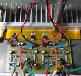
Thanks for comments , new and better pic's of A23 and A33 amplifiers .....🙂
Regards ,Alex
just when a man thinks that it could not be much better - you show up and post some new pictures! 🙂 i hope you will enjoj listening those amplifiers,and that you will write a word or two about sound impressions and some comparations wit other amplifiers you have listened.
great job!
I just etched some new A9 boards from this post. I realize there was a newer layout made but no foil was posted so I used this one. I'm cool without the 100n caps on the rails. I built the other A9 boards but I'm not crazy about the shape of them. I had them working but I shorted a couple pins and never could get the one channel working again so I am going to build them again on these boards. The one channel that is playing sounds good so I am looking forward to having a working pair.
Blessings, Terry
Blessings, Terry
Attachments

I just etched some new A9 boards from this post. I realize there was a newer layout made but no foil was posted so I used this one. I'm cool without the 100n caps on the rails. I built the other A9 boards but I'm not crazy about the shape of them. I had them working but I shorted a couple pins and never could get the one channel working again so I am going to build them again on these boards. The one channel that is playing sounds good so I am looking forward to having a working pair.
Blessings, Terry
Sorry i forgot to post PDF files of layout after i posted Sprint Layout file.
Regards, Sonal
Attachments
That's fine. This layout looks to follow the schematic fine. I probably would have built the newer version but I am not going to etch another set at this time.
Blessings, Terry
Blessings, Terry
That's fine. This layout looks to follow the schematic fine. I probably would have built the newer version but I am not going to etch another set at this time.
Blessings, Terry
Blessings, Terry
It sings! I finished populating the A9. What a sweet little amp. I would never have believed all this wonderful sound could come for those little MOSFETs. Really, really nice sounding. I'm done for the day but hopefully tomorrow I will have some time to hook up the scope and get some shots of some clipping and square waves. I'll also hook it up to the A/B setup and do some comparisons to some other amps.
Blessings, Terry
Blessings, Terry
Attachments
It sings! I finished populating the A9. What a sweet little amp. I would never have believed all this wonderful sound could come for those little MOSFETs. Really, really nice sounding. I'm done for the day but hopefully tomorrow I will have some time to hook up the scope and get some shots of some clipping and square waves. I'll also hook it up to the A/B setup and do some comparisons to some other amps.
Blessings, Terry
Nice work,
Regards
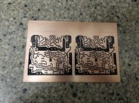
I notice the copper tracks are all loaded with plenty of lead. I've seen this before on some older commercial equipment.
Eventually there was a discussion on the effectiveness of using lead to thicken copper traces. The conclusion was that it wasn't worth it. Lead has only 7% the conductivity of copper. So with reasonably wide traces there would be no need to cover them with lead.
But if one feels comfortable about it , it shouldn't matter I guess.
If one really wants to have higher conductivity for high current tracks, a better method might be to solder a thick copper wire to the full length of the track ! I have seen that on some boards.
Last edited:

some people do it to prevent surface corrosion of copper and that sometimes even looks very nice. stillforgiven does it a bit more than it should,but that is the way he likes it so...
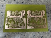
i tried do apply lead to a copper traces but i never did it nice and thin enough for my eye,so now i protect copper traces with destiled conifer resin (i dont know how it is called in english,actual thing is in a picture under post) mixed with acetone. after etching a pcb i drill the holes,than apply top side layout by toner transfer,clean copper traces one last time to get them shiny and than apply with the resin mentioned above.
that way i get a prety nice pcb,save copper from surface corrosion and prepare it for soldiering parts to a pcb. after i am done with soldiering,i clean copper side one more time with brush and acetone - and that is it. i have pcb´s about seven years old and they look very nice after all that time.
Attachments

Acetic acid doesn't corrode copper?
What is that yellow tape stuff you guys are using on the heatsinks under the transistors and how effective is it?
What is that yellow tape stuff you guys are using on the heatsinks under the transistors and how effective is it?
it is not acetic acid C2H4O2 Acetic acid - Wikipedia, the free encyclopedia
but acetone (CH3)2CO Acetone - Wikipedia, the free encyclopedia
and it does not corrode copper.
-----------------------------------
Capton tape...
but acetone (CH3)2CO Acetone - Wikipedia, the free encyclopedia
and it does not corrode copper.
-----------------------------------
Capton tape...
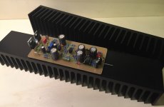
Very nice build!It sings! I finished populating the A9. What a sweet little amp. I would never have believed all this wonderful sound could come for those little MOSFETs. Really, really nice sounding. I'm done for the day but hopefully tomorrow I will have some time to hook up the scope and get some shots of some clipping and square waves. I'll also hook it up to the A/B setup and do some comparisons to some other amps.
Blessings, Terry
For the sound I absolutely agree. I will also finish the build of my A9. Heat sinks for a small pretty amplifier are already here 🙂
regards Olaf
Attachments
Rosin
Its called Rosin. Has many uses....Also used by violinists/Cellists, gymnasts, weightlifters.....
Vic
Its called Rosin. Has many uses....Also used by violinists/Cellists, gymnasts, weightlifters.....
Vic
some people do it to prevent surface corrosion of copper and that sometimes even looks very nice. stillforgiven does it a bit more than it should,but that is the way he likes it so...
i tried do apply lead to a copper traces but i never did it nice and thin enough for my eye,so now i protect copper traces with destiled conifer resin (i dont know how it is called in english,actual thing is in a picture under post) mixed with acetone. after etching a pcb i drill the holes,than apply top side layout by toner transfer,clean copper traces one last time to get them shiny and than apply with the resin mentioned above.
that way i get a prety nice pcb,save copper from surface corrosion and prepare it for soldiering parts to a pcb. after i am done with soldiering,i clean copper side one more time with brush and acetone - and that is it. i have pcb´s about seven years old and they look very nice after all that time.
A17++
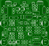
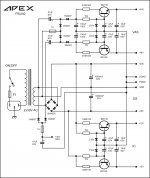
I listened a bit longer to the A17. It entered into the background here at the many new amplifiers. Meanwhile, I am of the opinion that it plays a bit lighter and more easier as the A33. Therefore, I made a PCB for the "big transistors" because I have a few pairs.
Because there was room on the PCB, I have added voltage regulators for the input and VAS. I do not know if I really integrate it so. Does anyone have a idea whether the circuit brings something?
regards Olaf
Attachments

Last edited:
I listened a bit longer to the A17. It entered into the background here at the many new amplifiers. Meanwhile, I am of the opinion that it plays a bit lighter and more easier as the A33. Therefore, I made a PCB for the "big transistors" because I have a few couples.
Because there was room on the PCB, I have added voltage regulators for the input and VAS. I do not know if I really integrate it so. Does anyone have a idea whether the circuit brings something?
regards Olaf
Use this PSU.
Regards
Last edited:
I was taught to tin all the traces when i built my first amp, an Elliot P101. I've been doing it ever since. It doesn't look as nice but I believe it helps insure connectivity and current carrying ability. The solder is not as thick as it appears in the picture. The yellow tape is Kapton tape. Recommended to me by Elliot when I built the P101. I bought a roll and have used it on every amp I've built. It is very thin and very tough.
Blessings, Terry
Blessings, Terry
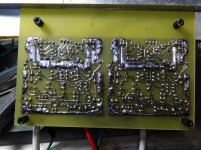
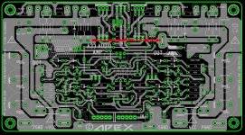
A33 pcb tested OK
A33 it's playing now ..... 😀 https://www.youtube.com/watch?v=SY3G4ZfwabA
I't was , one error which was corrected (forgot 100K resistor ) . Real tested PCB
attached below 🙂 ,more comments tomorrow .
Regards ,Alex
A33 it's playing now ..... 😀 https://www.youtube.com/watch?v=SY3G4ZfwabA
I't was , one error which was corrected (forgot 100K resistor ) . Real tested PCB
attached below 🙂 ,more comments tomorrow .
Regards ,Alex
Attachments
- Home
- Amplifiers
- Solid State
- 100W Ultimate Fidelity Amplifier