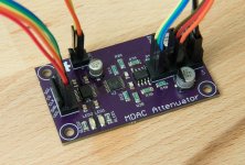
Just wanted to thank you for making this all available, Max. I just built up the MDAC Attenuator and it works great.
Just wanted to thank you for making this all available, Max. I just built up the MDAC Attenuator and it works great.
Excellent, glad you found it useful unrlmth! That's why I posted it all. Did you design your own PCB? Or use my design?
Excellent, glad you found it useful unrlmth! That's why I posted it all. Did you design your own PCB? Or use my design?
I used your PCB and similar parts from your BOM. I also ordered the input selector board, but haven't populated it yet.
Attachments
Hey Max
Have you considered using same power supply scheme for dac8812 as they do in datasheet (resistor divider and opamp buffer) since you were concerned at first and tried it with separate power supply.
Or maybe onboard linear regulator that uses same Vin as opamp.
Have you considered using same power supply scheme for dac8812 as they do in datasheet (resistor divider and opamp buffer) since you were concerned at first and tried it with separate power supply.
Or maybe onboard linear regulator that uses same Vin as opamp.
That's pretty neat, you can add a bluetooth module to your arduino and use my bt android remote app.
I did see that in the datasheet but to be honest I don't really understand what it is supposed to achieve. So no, I didn't try it. My implementation is just pretty standard for audio, having separate +/- 15V and 5V PSUs, like a DAC for example.Hey Max
Have you considered using same power supply scheme for dac8812 as they do in datasheet (resistor divider and opamp buffer) since you were concerned at first and tried it with separate power supply.
You mean regulate down to 5V from +15V? Some of the outer R2R DAC datasheets have this in them.Or maybe onboard linear regulator that uses same Vin as opamp.
Yes, that's the beauty of using Arduino, it's so customisable!That's pretty neat, you can add a bluetooth module to your arduino and use my bt android remote app.
I did see that in the datasheet but to be honest I don't really understand what it is supposed to achieve. So no, I didn't try it. My implementation is just pretty standard for audio, having separate +/- 15V and 5V PSUs, like a DAC for example.
You mean regulate down to 5V from +15V? Some of the outer R2R DAC datasheets have this in them.
I guess I am just complicating way too much. I was thinking of making my own board but not use same 5V PSU as arduino uses. I'll see how far I can get over weekend.
Even if something comes out of this I don't have any way to measure it.
That's possible, that's what I did with the isolator IC. I had noise issues and couldn't really work out why so I just bypassed the ADuM isolator IC and used a single PSU. You will need some other way to separate the power supplies though as the grounds need to join in some way.
Let us know if you try it 🙂
Let us know if you try it 🙂
Yeah kinda, I could just measure a 50hz spike when using the isolation. Details here:Oh so you had problems when you used two PSUs?
http://www.diyaudio.com/forums/digi...isolator-ic-between-micro-controller-dac.html
I couldn't really work out why though. Could have been my implementation, grounding, layout or something else. Either way, when using a single PSU, my measurements were very good anyway.
It took me just 3 months to get this to the point where I can post it here 🙂
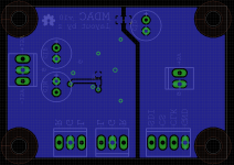
Anyway no isolation. I added onboard 5V psu. Digital and analog ground connected in one point (ferite bead or jumper probably).
How bad is this layout?
Still this is probably way over my ability to design and I should probably just use your design but I wanted to try if I can make something.
PCM measurement is 50x35mm.
Any comments
Attachments
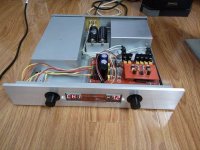
Pre my is with PGA2320.It took me just 3 months to get this to the point where I can post it here 🙂
Anyway no isolation. I added onboard 5V psu. Digital and analog ground connected in one point (ferite bead or jumper probably).
How bad is this layout?
Still this is probably way over my ability to design and I should probably just use your design but I wanted to try if I can make something.
PCM measurement is 50x35mm.
Any comments
Attachments
I don't get how this is related to zoidbergslo's post? Or the thread? Also the pic is too tiny to see anything anyway?Pre my is with PGA2320.
It took me just 3 months to get this to the point where I can post it here 🙂
Anyway no isolation. I added onboard 5V psu. Digital and analog ground connected in one point (ferite bead or jumper probably).
How bad is this layout?
Still this is probably way over my ability to design and I should probably just use your design but I wanted to try if I can make something.
PCM measurement is 50x35mm.
Any comments
Nice! Would help if you posted a schematic too. What ICs are you using? Have you tested this?
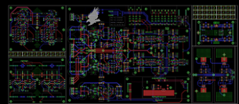
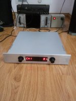
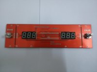
Sorry my English is bad, but this is my product in forum DIY VNAV.I don't get how this is related to zoidbergslo's post? Or the thread? Also the pic is too tiny to see anything anyway?
Nice! Would help if you posted a schematic too. What ICs are you using? Have you tested this?
Attachments

Some images used volumes of digital Pre PGA2320, I built in VNAV forum.Sorry my English is bad, but this is my product in forum DIY VNAV.
Attachments
Nice! Would help if you posted a schematic too. What ICs are you using? Have you tested this?
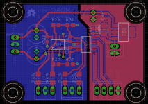
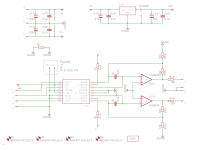
Well schematic is shameless copy of your design. I hope you don't mind.
IC1 would be AD8599 or maybe LME49720. IC2 is DAC8812 of course 🙂 IC3 is LT1129 regulator, I couldn't find any noise specification for it but I was more concerned about cooling of the regulator that is why I went with something in SOT223 package considering Vin-Vout is 10V. In DAC datasheet I only found power consumption when there is no input (5uA) so I didn't know how much current will it actually need.
All resistors will be Susumu RG, big caps are oscons and and regulator out cap will be poscap.
BOM right now is almost 40eur.
I have not yet tested this PCB. I am getting my Mouser order together. I am hoping to order in two weeks time.
Attachments
Of course not, that's why I posted it.Well schematic is shameless copy of your design. I hope you don't mind.
Sounds good. Post results when complete!IC1 would be AD8599 or maybe LME49720. IC2 is DAC8812 of course 🙂 IC3 is LT1129 regulator, I couldn't find any noise specification for it but I was more concerned about cooling of the regulator that is why I went with something in SOT223 package considering Vin-Vout is 10V. In DAC datasheet I only found power consumption when there is no input (5uA) so I didn't know how much current will it actually need.
All resistors will be Susumu RG, big caps are oscons and and regulator out cap will be poscap.
BOM right now is almost 40eur.
I have not yet tested this PCB. I am getting my Mouser order together. I am hoping to order in two weeks time.
6 inputs?
Hi,
Thanks for all information you share to all of us.
I planed to build the same solution and have some questions;
1/ Need for 6 inputs -any ideas about to expand from 3 to 6 inputs?
2/Any ideas about implemented a balance function? Balance between Left and Right?
Thanks in advance!
Hi,
Thanks for all information you share to all of us.
I planed to build the same solution and have some questions;
1/ Need for 6 inputs -any ideas about to expand from 3 to 6 inputs?
2/Any ideas about implemented a balance function? Balance between Left and Right?
Thanks in advance!
Since DAC has two independent sides you could control each separately to get one side louder than the other or did I miss something in datasheet.
As for inputs you could go with something like MCP23S17 instead of MCP23S08 and just use two ULN2803A.
As for inputs you could go with something like MCP23S17 instead of MCP23S08 and just use two ULN2803A.
- Home
- Source & Line
- Analog Line Level
- Building a complete Preamp with an Arduino, remote, volume and input control