Attached is my first trail to convert your 240-Volt 5-Volt Power Supply Eagle files to 120-Volt 5-Volt Power Supply Eagle files. I know NOTHING about Eagle.😡
Yes, both Eagle and KiCad are hard and frustrating to learn to use 😀
Forgot to attach my zip file, is attached below.
The zip file you attached is empty. Furthermore, could you post in this thread about changes to the design? To keep on topic:
A simple LT1763 based 5V PSU
Please look over my Eagle Conversion to 120Volts Again
I fixed my zip file and posted it to the correct thread. Sorry about the mix-up.😉
I fixed my zip file and posted it to the correct thread. Sorry about the mix-up.😉
Please look over my Eagle Conversion to 120Volts
I also posted another Eagle 120 Volt AC on the following thread:
A simple but low noise LT1761/LT1964 PSU design
Please look over my 120 Volt AC changes on this design. 😉
I also posted another Eagle 120 Volt AC on the following thread:
A simple but low noise LT1761/LT1964 PSU design
Please look over my 120 Volt AC changes on this design. 😉
Hey Exelixis,
Sorry for the late reply. I don't know why the thread subscription notification system is so flakey on these forums...
Sure but you will need to power both both boards and have arduino code controlling the mute relay. TBH if you only want relay mute then maybe just implement that yourself separate from the attenuator. It would be a pain to use the input selector just for the mute feature.
Sure, post your code with a specific question.
I can check. I am actually still working on this preamp 🙂
Both PCBs need power to run the relays etc. If you are just interested in the attenuator then just don't use or attach the input selector PCB. They can both be run separately easily.
Hi again Maxw,
It's been a while since my post and I wasn't aware of your answer. I've taken a closer look at your code and found out how you control the input selector relays, so I will imitate that to control the muting relay as well, by also changing the muting function to operate that relay and not set the volume to zero. Am I right?
What concerns me most, is that if this design has the usual problem of pops heard when many relays disengage. What is your experience so far?
I will imitate that to control the muting relay as well, by also changing the muting function to operate that relay and not set the volume to zero. Am I right?
Yes, correct. I think the MDAC volume does not go to all the way to 0, just a very low volume.
What concerns me most, is that if this design has the usual problem of pops heard when many relays disengage. What is your experience so far?
I've never had this problem with input selectors. Only with relayed based attenuators.
My new problem is that I can't solder cable onto the ground part of these connectors:
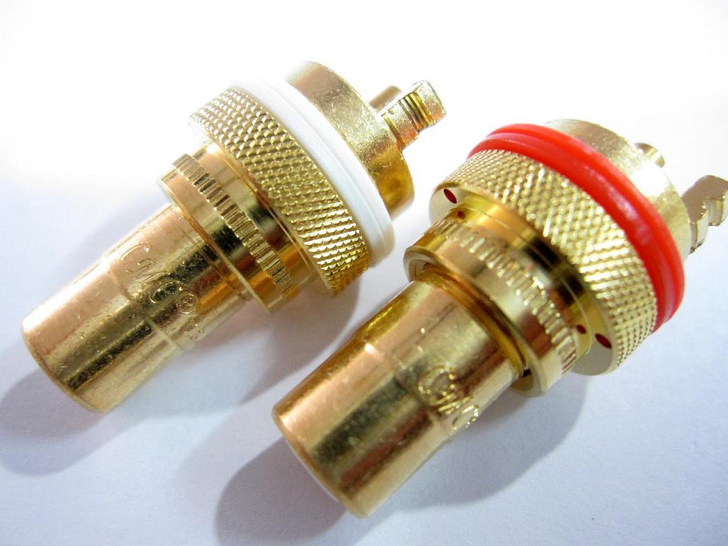
Even with my 70W Hakko soldering iron I can't get enough heat into the connector to get the solder to stick properly as the connector is such a large solid piece of metal 🙁
Any body else had this problem?
Realizing this is a response to a VERY old post, I'm adding this in case it helps anyone. When soldering large parts or parts to circuit boards with large ground traces, try this: clean with a brass brush, coat with rosin flux and try to contain the heat in the area of the joint - for rear panel connectors, they should be laying down with the terminals sticking through the PC board on top of them.
Hi,
I'm very interested and impressed by this project, I wanted to use the MDAC module to create a 6 channel volume control, in your opinion is it possible ... obviously with some modifications and additions?
In what sense can drive headphones?
How?
I'm very interested and impressed by this project, I wanted to use the MDAC module to create a 6 channel volume control, in your opinion is it possible ... obviously with some modifications and additions?
In what sense can drive headphones?
How?
Hi,
I'm very interested and impressed by this project, I wanted to use the MDAC module to create a 6 channel volume control, in your opinion is it possible
Sure. Just build 3 of them and connect them to an Arudino using SPI.
... obviously with some modifications and additions?
I don't think any changes are required to the module, just your code.
In what sense can drive headphones? How?
The opamp in the MDAC attenuator is driving the headphones. You can check the datasheet and work it out.
FYI this thread is for my much older project. My newer project is here: My new preamp design: Arduino, 6 input selector, MDAC attenuator, IR etc
Sure. Just build 3 of them and connect them to an Arudino using SPI.
I don't think any changes are required to the module, just your code.
The opamp in the MDAC attenuator is driving the headphones. You can check the datasheet and work it out.
FYI this thread is for my much older project. My newer project is here: My new preamp design: Arduino, 6 input selector, MDAC attenuator, IR etc
Perfect!!!
very nice, I get to work.
really many thanks, really good job!
A very interesting thread.
@maxw
Do you have THD measurements versus audio level ?
Have you worked with the TI evaluation kit EV8801/11EVM for the DAC8811 ?
Why you did not use OPA2277, an excellent precision amplifier ?
TI uses OPA227 with DAC8811 on their evaluation board.
@maxw
Do you have THD measurements versus audio level ?
Have you worked with the TI evaluation kit EV8801/11EVM for the DAC8811 ?
Why you did not use OPA2277, an excellent precision amplifier ?
TI uses OPA227 with DAC8811 on their evaluation board.
A very interesting thread.
@maxw
Do you have THD measurements versus audio level ?
I only have what I posted. It was done with RMAA or Arta and a Emu USB sound card.
Have you worked with the TI evaluation kit EV8801/11EVM for the DAC8811 ?
Nope.
Why you did not use OPA2277, an excellent precision amplifier ?
TI uses OPA227 with DAC8811 on their evaluation board.
No specific reason. There's many options to choose from but I think I chose the AD8599 because it was recommended in an app note from Analog devices but I can't remember exactly. I don't think it matters too much, you're unlikely to hear any difference or measure a difference with a USB sound card 🙂
Congrats on your design. I saw the earlier iterations, really liked them and had them on my to-do list for the preamp I'm going to build, but these are undoubtedly tidier. I'm curious about the attenuator just to see how it behaves, it's just such a neat idea. There's no reason it couldn't be doubled up for a balanced system?
Dumb newbie question: This'll be the first time I've ever taken Eagle files and generated Gerbers to send to (probably) pcbway. I opened your board files in Eagle, selected Generate CAM data and let Eagle have at it. It seemed deceptively simple, so much so, I was immediately suspicious I'd got something wrong...
Is there anything I've missed or should I get back the boards I'm expecting 🙂
May I suggest the TI evaluation kit EV8801/11EVM for the DAC8811 ?
With this you can readily go at experimenting with an attenuator based on a 16 bit MDAC.
You have everything but the Arduino or Rasberry Pi to drive it.
With this you can readily go at experimenting with an attenuator based on a 16 bit MDAC.
You have everything but the Arduino or Rasberry Pi to drive it.
Congrats on your design
Thanks but this thread is actually my older version. My new design is in this thread: My new preamp design: Arduino, 6 input selector, MDAC attenuator, IR etc
There's no reason it couldn't be doubled up for a balanced system?
I think you can do it with one attenuator per left/right with balanced.
Dumb newbie question: This'll be the first time I've ever taken Eagle files and generated Gerbers to send to (probably) pcbway. I opened your board files in Eagle, selected Generate CAM data and let Eagle have at it.
I think Eagle CAM process is too complicated in my experience. You don't need to do it, you can just upload BRD files directly to services like OSHPark. It's much easier 🙂
Thanks for the advice. This is all new for me. I made my living writing software on Windows and Android, but fancied branching out to try embedded/arduino/device programming and thought that this would make an interesting newbie project.
But the learning curve is... ouch.
But the learning curve is... ouch.
Thanks for the advice. This is all new for me. I made my living writing software on Windows and Android, but fancied branching out to try embedded/arduino/device programming and thought that this would make an interesting newbie project.
But the learning curve is... ouch.
You'll be fine, just keep at it 🙂 I recommend the CircuitPython boards from Adafruit. They are much more modern and easier to use than the standard Arduino boards. My latest preamp software is written all in python and it's so much nicer to work with.
I can do C++ and C, but I loath Python I had a boss that was keen on it, and was forced into using it. I never really recovered from the idea that indentation meant something. Then again, it's the coming thing for this sort of work, so I'll go with the flow...
What're you using for your dev environment? I've been used to Intellij for my Java/Android work and it appears that the Intellij Pycharm add-in won't do Circuit Python. It looked like there was Mu(?) but that was barely better than a text editor...
I already have a Feather m0 I've been fiddling with on breadboard+C. I'll grit my teeth and wade into Python 🙂
One final question: if I wanted to use your original relay stepped attenuator instead of the digital version it would need code changes, but there's no fundamental incompatibility. No particular reason for doing so, just curiosity...
Once again, many thanks for the help. Been to github and looked at your latest version. A really nice complete system, I'll be ordering PCBs from Oshpark as you suggest.
I never really recovered from the idea that indentation meant something
If you put up with annoying semi-colons having to terminate every line then I'm sure you can cope with python indentation 😅
What're you using for your dev environment?
I use Atom but Intellij will work fine, just install python plugin.
One final question: if I wanted to use your original relay stepped attenuator instead of the digital version it would need code changes, but there's no fundamental incompatibility. No particular reason for doing so, just curiosity...
It would work fine but would require some small code changes, yes.
Once again, many thanks for the help. Been to github and looked at your latest version. A really nice complete system, I'll be ordering PCBs from Oshpark as you suggest.
Thank you 🙏
I feel the choice of circuit python is a personal preference. For us old timers who were weaned on machine code programming, using C++ on an Arduino is not an issue. If you prefer C++ to Python (which you loath) then your view might differ from Maxw. The Atmeg 328 (eg. the Arduino nano) is cheap as chips and perfectly up to the job. Python runs on fewer boards and usually generates bulkier code; these fewer boards are more expensive, although many would say they are still quite affordable.
So not everyone is convinced that circuit python is “easier to use”; for some it is no difference. So if you prefer C++, you could choose to play to your strengths.
Oh, and yes, I can do python when called upon.
Geoff
So not everyone is convinced that circuit python is “easier to use”; for some it is no difference. So if you prefer C++, you could choose to play to your strengths.
Oh, and yes, I can do python when called upon.
Geoff
- Home
- Source & Line
- Analog Line Level
- Building a complete Preamp with an Arduino, remote, volume and input control