In other words, I don't see how you mute one output when you listen to the other. Do you install a switch ? 😕
In other words, I don't see how you mute one output when you listen to the other. Do you install a switch ? 😕
My method is simple, I don't switch on the power amp wile listening to the headphones, or I don't connect the headphone wile listening the loudspeakers. You can use a switch, it should be quite simple to do that.
Interesting thread, just read the whole of it....
Richard Marsh with his amazing collection of Audio Measurement Equipment:
Post #322 http://www.diyaudio.com/forums/solid-state/235695-no-nfb-line-amp-gainwire-mk2-33.html#post3828835
offered to do actual measurements. But I didn't see any posted, was it ever done, and if, where are they ?
Richard Marsh with his amazing collection of Audio Measurement Equipment:
Post #322 http://www.diyaudio.com/forums/solid-state/235695-no-nfb-line-amp-gainwire-mk2-33.html#post3828835
offered to do actual measurements. But I didn't see any posted, was it ever done, and if, where are they ?
Interesting thread, just read the whole of it....
Richard Marsh with his amazing collection of Audio Measurement Equipment:
Post #322 http://www.diyaudio.com/forums/solid-state/235695-no-nfb-line-amp-gainwire-mk2-33.html#post3828835
offered to do actual measurements. But I didn't see any posted, was it ever done, and if, where are they ?
How much I know the measurement was never done. I've sent one PCB board to him, but he never assembled it. Richard prefare finished board.
OK, I'll do like that at first.
This afternoon I've received the isolation kit for the regulators. 🙂
Nicola
This afternoon I've received the isolation kit for the regulators. 🙂
Nicola
Dadod,
I must say, it's very nice to see someone taking a radically different approach to the conventional loop feedback amplifiers!. The other nice part is that this can be used with most cfa from the vas collectors. I have recently used this in my current feedback preamp and the results are nothing short of outstanding in imaging and vitality to the music, along with the best bass I've heard in a while. Without a dc servo offset is techy and can stick to the rails upon startup, however I used cap coupling which allows none of these issues. Dadod, have you built this?, I hope so, if not you should, well worth the sound 🙂.
Colin
Dadod,
I must say, it's very nice to see someone taking a radically different approach to the conventional loop feedback amplifiers!. The other nice part is that this can be used with most cfa from the vas collectors. I have recently used this in my current feedback preamp and the results are nothing short of outstanding in imaging and vitality to the music, along with the best bass I've heard in a while. Without a dc servo offset is techy and can stick to the rails upon startup, however I used cap coupling which allows none of these issues. Dadod, have you built this?, I hope so, if not you should, well worth the sound 🙂.
Colin
Thank you Colin, If you have read this thread then you must noticed my prototype I have built, and some others, I hope, who bought the PCB, but not so much comments about the result. I suppose some will come after this summer finished. Here in Croatia the summer is over to soon with to much rain.
Damir
I get +15V and -15V on the power supply section! 😎
Heatsinks are very hot...
I go ahead now.
Good, now all power is disipated inside the power supply as the preamp part is not yet connected, it should be less hot after preamp is assembled.
Hi Damir,
Still working on finishing the thread, but was more inspired by just the current conveyor with gain concept as a general whole. My circuit shares similarities but is simpler, but the concept is fabulous sounding, those used to loop feedback will be in for quite a surprise!. I still manage below 0.01% monotonically decreasing with an utter absense of anything above h4 ,but it's presentation that has floored me.
Colin
Hi Damir,
Still working on finishing the thread, but was more inspired by just the current conveyor with gain concept as a general whole. My circuit shares similarities but is simpler, but the concept is fabulous sounding, those used to loop feedback will be in for quite a surprise!. I still manage below 0.01% monotonically decreasing with an utter absense of anything above h4 ,but it's presentation that has floored me.
Colin
Hi Colin,
This current conveyor can work with no global negative feedback or in CFA mode, when the output buffer is in the negative feedback loop too, and I am pleasantlly suppraised with the sound and it's presentation how you called it.
If you interested in more current conveyors, look for my non GNFB class B power amp. There is one case when the input gain stage (current conveyor) is in the own NFB loop. For that I needed aditional buffer.
Damir
Hi Dado,
Populating the PCB is near completion. Critical matched transistors must be selected now... 😀
R37 is not in the BOM. Do you confirm 470R ?
About heatsinks: are BD139 and BD140 very hot when running ?
Nicola
Populating the PCB is near completion. Critical matched transistors must be selected now... 😀
R37 is not in the BOM. Do you confirm 470R ?
About heatsinks: are BD139 and BD140 very hot when running ?
Nicola
Hi Dado,
Populating the PCB is near completion. Critical matched transistors must be selected now... 😀
R37 is not in the BOM. Do you confirm 470R ?
About heatsinks: are BD139 and BD140 very hot when running ?
Nicola
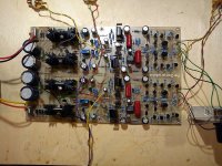
Nicola, R37 is 470R.
BD139/140 could get a bit hot, I used small heath sinks, look the photo, or use small U shaped alu heath sink bolted directly on the transistors.
Damir
Attachments
Hi Dadod,
Finally the preamp card is ready 😎
Now I'm using the headphones only and the music is playing on both channels 🙂
However it is too loud and I cannot set lower volume. I can change it but in very small margin. I have disconnected Gnd (pin 3) of potentiometer (both channels) because the preamp doesn't like it. I don't know why 😕. The pot is TKD 2CP-2500 50K. Pin 1 (1) is connected to P1, Pin 2 (2) to P2 and Pin 3 (C) to gnd.
Hi Dadod,
Finally the preamp card is ready 😎
Now I'm using the headphones only and the music is playing on both channels 🙂
However it is too loud and I cannot set lower volume. I can change it but in very small margin. I have disconnected Gnd (pin 3) of potentiometer (both channels) because the preamp doesn't like it. I don't know why 😕. The pot is TKD 2CP-2500 50K. Pin 1 (1) is connected to P1, Pin 2 (2) to P2 and Pin 3 (C) to gnd.
Hi Nicola,
I think that I showed ones the schematic with wrong potentiometer connection. P1, P2 and gnd are PCB silkscreen markings.
Here is how it should be connected, sorry for confusion.
Damir
Attachments

Never mind: now the music is playing at usual volume and I can set it normally 😉
First tests are done with the headphones (Sony MDR CD1700) in CFA mode, Teac VRDS-25 CD player and external DAC.
After three hours, I can say about this preamp: great clarity and transparency, very detailed but not overanalytical, deep bass and good depth. No harshness at all: if any, this preamp doesn't cause it.
I find some light hum, but the R-core transformer is very close (1-2cm) to the preamp and the cables are not firmly connected. When I move the transformer away, the hum goes down.
Next step: listening through loudspeakers to confirm this wonderful experience. 🙂
Never mind: now the music is playing at usual volume and I can set it normally 😉
First tests are done with the headphones (Sony MDR CD1700) in CFA mode, Teac VRDS-25 CD player and external DAC.
After three hours, I can say about this preamp: great clarity and transparency, very detailed but not overanalytical, deep bass and good depth. No harshness at all: if any, this preamp doesn't cause it.
I find some light hum, but the R-core transformer is very close (1-2cm) to the preamp and the cables are not firmly connected. When I move the transformer away, the hum goes down.
Next step: listening through loudspeakers to confirm this wonderful experience. 🙂
Nicola, very nice you succeeded. I did not have any hum in mine prototype, so it should be possible to get that with careful positioning. I used ordinary non shielded wires, but I used it in a wooden box, if you put it in the metal box and connect the preamp ground to the box, be careful, use a ground loop breaker look here Earthing (Grounding) Your Hi-Fi - Tricks and Techniques figure 4.
What mode you prefer non GNFB, or CFA?
Damir
After breaking-in for several hours, the preamp is opening up. 🙂
It is very difficult to say which mode I prefer in my setup. The CFA mode has greater clarity and more details, but the margin is small. It is very nice to have both modes!
Usually I listen through loudspeakers instead of headphones. So I'll give a little bit more detailed listening report when connecting loudspeakers (including about modes).
I suppose that replacing the current pot with resistance attenuator will give a higher transparency. However the TKD pot does the job nicely
Do you think that going from 50K to 10K potentiometer is a good move ?
I find that having this preamp in my system is a real and appreciated gift.
Nicola
Last edited:
After breaking-in for several hours, the preamp is opening up. 🙂
It is very difficult to say which mode I prefer in my setup. The CFA mode has greater clarity and more details, but the margin is small. It is very nice to have both modes!
Usually I listen through loudspeakers instead of headphones. So I'll give a little bit more detailed listening report when connecting loudspeakers (including about modes).
I suppose that replacing the current pot with resistance attenuator will give a higher transparency. However the TKD pot does the job nicely
Do you think that going from 50K to 10K potentiometer is a good move ?
I find that having this preamp in my system is a real and appreciated gift.
Nicola
I am not sure about different between 50k and 10k potentiometer as I tried 10k only, probably less hum with 10k.
Nicola, how is going your work on the power amp?
Damir
PS. with low impedance headphones difference between CFA an non GNFB mode is more pronounced, working as a line preamp or with high (300 ohm or more) impedance headphones it will be not easy to hear the difference, at list I couldn't.
Last edited:
hum practically disappears (listening in the silence of night) when I move the transformer about 12-16cm 🙂D) from the board.
When listening tests with preamp are finished, I'll start (I hope so...) populating one amp PCB. In the same time, I'll design the preamp box. What is the exact distance between preamp mounting holes ?
When listening tests with preamp are finished, I'll start (I hope so...) populating one amp PCB. In the same time, I'll design the preamp box. What is the exact distance between preamp mounting holes ?
- Status
- Not open for further replies.
- Home
- Amplifiers
- Solid State
- No NFB line amp (GainWire mk2)