The IRF's need much more bias spread than the Laterals, they are also more critical in terms of thermal management, for this purpose I would strongly recommend the Lateral feats (They are sold through Profusion they also handle web sales in small quantity)
The IRF's need much more bias spread than the Laterals, they are also more critical in terms of thermal management, for this purpose I would strongly recommend the Lateral feats (They are sold through Profusion they also handle web sales in small quantity)
In the Prufusion site I can only see ECX10N20R and ECX10P20R.... should I order those ?
How do I determine and set the bias current on your schematic ?
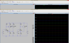
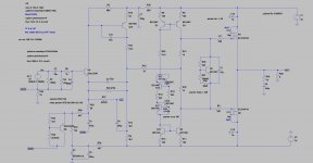
Here's is a lat-fet version. Distortion spectra is good, thermals are good too.
Can you share the lateral model, please?
Here are some laterals :CordellAudio.com - SPICE Models
I already have them. But he use Exicon lateral mosfet.
Here are the models I use, for a follower i don't really think that it matters which model you use. as you will need to do real world adjustments to the Idle. and still with lat-fets it will be good to have the VBE transistor thermally close the the OPS.
.MODEL 2SJ162 PMOS (VTO=842.193M KP=20U L=2U W=21.3317M GAMMA=0 PHI=600M LAMBDA=20.7067M RD=837.199M CBD=2.96862N IS=10F CGSO=1.13517N CGDO=1.13517N TOX=0 NSUB=0 TPG=1 UO=600 RG=50 RDS=1MEG )
.MODEL 2SK1058 NMOS (VTO=403.969M KP=20U L=2U W=29.7482M GAMMA=0 PHI=600M LAMBDA=184.988F RD=60.8251M CBD=2.56138N IS=10F CGSO=1.13517N CGDO=1.13517N TOX=0 NSUB=0 TPG=1 UO=600 RG=50 RDS=1MEG )
.MODEL ECX10N16 NMOS (LEVEL=1 VTO=-66.415M KP=20U L=2U W=76.3794M GAMMA=0 PHI=600M LAMBDA=3.44617M RD=244.181M RS=178.517M IS=10F CGSO=100P CGDO=100P TOX=0 NSUB=0 TPG=1 UO=600 RG=367.902 RDS=16.0012K )
.MODEL ECX10P16 PMOS (LEVEL=1 VTO=56.1959M KP=20U L=2U W=49.9039M GAMMA=0 PHI=600M LAMBDA=16.6941M RD=458.28M RS=214.674M CBD=1.00674N IS=10F CGSO=100P CGDO=100P TOX=0 NSUB=0 TPG=1 UO=600 RG=35.8793 RDS=1MEG )
Thank you so much Miib
It sims much better then my other atempts.... I will do build it as soon as I get the fets.
Please let me know if I can use ECX10N20R and ECX10P20R.
PS: I have read most N and P fets have different Ciss so we should use different values for gate stoppers.... does it matter here ?
It sims much better then my other atempts.... I will do build it as soon as I get the fets.
Please let me know if I can use ECX10N20R and ECX10P20R.
PS: I have read most N and P fets have different Ciss so we should use different values for gate stoppers.... does it matter here ?
very little, but you can roll the turnoff so it symmetric by adding different resistors.
I think all of them are suitable and use able. I believe they are the same, just differnt packing. the TO-3's are really rugged.
I think all of them are suitable and use able. I believe they are the same, just differnt packing. the TO-3's are really rugged.
Thank you.
I believe this one will sound really good 🙂
Will try to determine the optimal Rgate and post here
I believe this one will sound really good 🙂
Will try to determine the optimal Rgate and post here
They only make the stronger types because out of the process most where stronger anyway.
Laterals are forgiving you know.
Laterals are forgiving you know.
I am looking forward to it.
Out of the swamp came human kind from humble beginnings.....
Ashes to ashes, dust to dust.
Out of the swamp came human kind from humble beginnings.....
Ashes to ashes, dust to dust.
Miib
How can I practically measure output idling current with this layout that does not have ballast resistors (source resistors) ?
How can I practically measure output idling current with this layout that does not have ballast resistors (source resistors) ?
- Home
- Amplifiers
- Solid State
- Assemblage Power Amp