What are the optional BD140 and BD139 for ?
Output current limiting (shortcut protection 🙂).
Here is a more sofisticated clipper that compresses before it cuts off :http://www.diyaudio.com/forums/analog-line-level/222139-soft-clipper-central-station.html
There is no thermal protection, and the Re's of 1ohm are to high (try doing a 'wingspread' on those). The gain is set to 10x, that is a little bit low (I think, e.g. 10 * 1.4V = 14V and the PSU is 24V, so a gain of 15x would be more fitting).
I own this one :Elite Series Quad
For the price it costs it is a very good amp.
I use it as reality check.
For the price it costs it is a very good amp.
I use it as reality check.
Output current limiting (shortcut protection 🙂).
Would you care to explain how it works ?
What are those diodes ?
My nobrainer blew one channel (again) when I switched on the manley tube preamp I am working on. (During power on the uge output caps take some time to charge and output offset goes from -10 to + 34v).
Now I must repair it (when I get some more d44 d45h11).
With a new configuration I got a much cleaner FFT at 1v input.
But idling base voltages on the output drivers came down from +-1.4v to around +-650mV
How low can I set the base voltages on the drivers ?
But idling base voltages on the output drivers came down from +-1.4v to around +-650mV
How low can I set the base voltages on the drivers ?
Attachments

Would you care to explain how it works ?
What are those diodes ?
My nobrainer blew one channel (again) when I switched on the manley tube preamp I am working on. (During power on the uge output caps take some time to charge and output offset goes from -10 to + 34v).
Now I must repair it (when I get some more d44 d45h11).
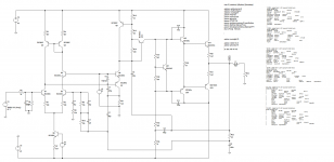
As voltage builds over R3/R4 and gets to Vbe+Vd ( = +- 1.3V) the transistor starts to short (sort of) the base current of the power devices, and directs it into the rail. As you can see this will probably kill the drivers 🙂 (unintentionally, this is not a very good amplifier (as noted before)).
With a new configuration I got a much cleaner FFT at 1v input.
But idling base voltages on the output drivers came down from +-1.4v to around +-650mV
How low can I set the base voltages on the drivers ?
What do you mean by 'set the base voltages on the drivers', be more specific 🙂
Would you care to explain how it works ?
What are those diodes ?
My nobrainer blew one channel (again) when I switched on the manley tube preamp I am working on. (During power on the uge output caps take some time to charge and output offset goes from -10 to + 34v).
Now I must repair it (when I get some more d44 d45h11).
You should not input DC into a DC coupled amplifier! Use a smaller capacitor (that may not work, if the lower frequency is set to 10Hz then the amplifier needs to survive 100mS of the rail voltage into the load) (the load will not like it). Use a output transformer on your pre-amp. Have a relay on the pre-amp that disconnects it from the amplifier as long as there is DC on the output.
You should not input DC into a DC coupled amplifier! Use a smaller capacitor (that may not work, if the lower frequency is set to 10Hz then the amplifier needs to survive 100mS of the rail voltage into the load) (the load will not like it). Use a output transformer on your pre-amp. Have a relay on the pre-amp that disconnects it from the amplifier as long as there is DC on the output.
There is a uge output cap on the manley preamp.
This preamp must be switched on 1 min before the power amp is switched on, otherwise there is a "thump" on the speakers.... in this case there is smoke in the nobrainer 🙂🙂
Now I have rebuilt the nobrainer and put fuses on the rails 🙂
What do you mean by 'set the base voltages on the drivers', be more specific 🙂
In the nobrainer, I have +-1.4v on the bases of the drivers in order to get iddle at 180mA on the output trannies.
In my new simulation, I only need +-600mV to get the same current on the output trannies.
What I need to know is what is the minimum base voltage on the drivers that keeps them conducting.
My questions might seem really basic to most of you guys.... anyway, i found that a CFP needs only around 625mv in the base to start conducting..... so everything is ok for now 🙂
To whom it may concern :http://www.epanorama.net/sff/Audio/Circuits/Pre-Amps/60W NDFL Power Amplifier.pdf
It seems interesting Joachim, here is the ltspice file of the Cherry amplifier , if people want to make some tests.
PS: Q5 have to be renamed BC550C
PS: Q5 have to be renamed BC550C
Attachments
Last edited:
Many thanks.
It is rather simple and trades better in band measurements for a bit less performance over 20kHz.
It is certainly an alternative to TMC for example.
I do not know a commercial amp that uses it.
I think Halcro and Mace adopted some ideas.
It is rather simple and trades better in band measurements for a bit less performance over 20kHz.
It is certainly an alternative to TMC for example.
I do not know a commercial amp that uses it.
I think Halcro and Mace adopted some ideas.
- Status
- Not open for further replies.
- Home
- Source & Line
- Analogue Source
- JG´s Nobrainer and Nobrainer Discrete