Sir, I want to find a 43k resistor is very hard .. Can it be replaced with another resistor .. Please help.. Tank's
Sir, I want to find a 43k resistor is very hard .. Can it be replaced with another resistor .. Please help.. Tank's
Use 33k and 10k in series
43k is a standard E24 resistor value. Almost every retailer stocks E24 resistors from 10r to 1M0
E24 Resistor Sizes
1.0 Ω 10 Ω 100 Ω 1.0 kΩ 10 kΩ 100 kΩ 1.0 MΩ
1.1 Ω 11 Ω 110 Ω 1.1 kΩ 11 kΩ 110 kΩ 1.1 MΩ
1.2 Ω 12 Ω 120 Ω 1.2 kΩ 12 kΩ 120 kΩ 1.2 MΩ
1.3 Ω 13 Ω 130 Ω 1.3 kΩ 13 kΩ 130 kΩ 1.3 MΩ
1.5 Ω 15 Ω 150 Ω 1.5 kΩ 15 kΩ 150 kΩ 1.5 MΩ
1.6 Ω 16 Ω 160 Ω 1.6 kΩ 16 kΩ 160 kΩ 1.6 MΩ
1.8 Ω 18 Ω 180 Ω 1.8 kΩ 18 kΩ 180 kΩ 1.8 MΩ
2.0 Ω 20 Ω 200 Ω 2.0 kΩ 20 kΩ 200 kΩ 2.0 MΩ
2.2 Ω 22 Ω 220 Ω 2.2 kΩ 22 kΩ 220 kΩ 2.2 MΩ
2.4 Ω 24 Ω 240 Ω 2.4 kΩ 24 kΩ 240 kΩ 2.4 MΩ
2.7 Ω 27 Ω 270 Ω 2.7 kΩ 27 kΩ 270 kΩ 2.7 MΩ
3.0 Ω 30 Ω 300 Ω 3.0 kΩ 30 kΩ 300 kΩ 3.0 MΩ
3.3 Ω 33 Ω 330 Ω 3.3 kΩ 33 kΩ 330 kΩ 3.3 MΩ
3.6 Ω 36 Ω 360 Ω 3.6 kΩ 36 kΩ 360 kΩ 3.6 MΩ
3.9 Ω 39 Ω 390 Ω 3.9 kΩ 39 kΩ 390 kΩ 3.9 MΩ
4.3 Ω 43 Ω 430 Ω 4.3 kΩ 43 kΩ 430 kΩ 4.3 MΩ
4.7 Ω 47 Ω 470 Ω 4.7 kΩ 47 kΩ 470 kΩ 4.7 MΩ
5.1 Ω 51 Ω 510 Ω 5.1 kΩ 51 kΩ 510 kΩ 5.1 MΩ
5.6 Ω 56 Ω 560 Ω 5.6 kΩ 56 kΩ 560 kΩ 5.6 MΩ
6.2 Ω 62 Ω 620 Ω 6.2 kΩ 62 kΩ 620 kΩ 6.2 MΩ
6.8 Ω 68 Ω 680 Ω 6.8 kΩ 68 kΩ 680 kΩ 6.8 MΩ
7.5 Ω 75 Ω 750 Ω 7.5 kΩ 75 kΩ 750 kΩ 7.5 MΩ
8.2 Ω 82 Ω 820 Ω 8.2 kΩ 82 kΩ 820 kΩ 8.2 MΩ
9.1 Ω 91 Ω 910 Ω 9.1 kΩ 91 kΩ 910 kΩ 9.1 MΩ
dear apex,For better sound use Regulated PSU.
give me its pcb.thanks
Fuses blowing instantly
Hi
I have assembled one channel and tested it with a center-tapped transformer rectified to DC at approximately +32V/0V/-32V
Both 5 amps fuses blows the second I power it up. What could be the problem? I've attached a couple of pictues of my PCB.
Hi
I have assembled one channel and tested it with a center-tapped transformer rectified to DC at approximately +32V/0V/-32V
Both 5 amps fuses blows the second I power it up. What could be the problem? I've attached a couple of pictues of my PCB.
An externally hosted image should be here but it was not working when we last tested it.
An externally hosted image should be here but it was not working when we last tested it.
An externally hosted image should be here but it was not working when we last tested it.
i can't see heatsink.... you tried this without heatsink?
Was the idle current accordingly adjusted
Put resistors 10-20R instead of fuses .
put a lamp (normal lamp 100w)in series with transformers primary side.ATTENTION HIGH VOLTAGE. DANGER
This lamp must glow when amplifier switched on and go dark after a little.
If this continue glow there is a problem somewhere.
Measure voltage on resistors(instead of fuses ,you must expect a low voltage here(300mV)or something UNDER NORMAL CONTITIONS.
If you find a high voltage here 3....5V or higher you must expect problems and you must check for faults.
It's posible now you have some burned out transistors.
You must check these and replace if these are faults
Last edited:
Wrong polarity diode in negative rail.Hi
I have assembled one channel and tested it with a center-tapped transformer rectified to DC at approximately +32V/0V/-32V
Both 5 amps fuses blows the second I power it up. What could be the problem? I've attached a couple of pictues of my PCB.
An externally hosted image should be here but it was not working when we last tested it.
Don't forget to connect input ground to psu ground.
Wrong polarity diode in negative rail.
Don't forget to connect input ground to psu ground.
I did connect the signal ground to PSU ground when I tested, so that should be OK - I will try reversing the polarity of the 1N4007 diode near te 2SA1943.
i can't see heatsink.... you tried this without heatsink?
Was the idle current accordingly adjusted
Put resistors 10-20R instead of fuses .
put a lamp (normal lamp 100w)in series with transformers primary side.ATTENTION HIGH VOLTAGE. DANGER
This lamp must glow when amplifier switched on and go dark after a little.
If this continue glow there is a problem somewhere.
Measure voltage on resistors(instead of fuses ,you must expect a low voltage here(300mV)or something UNDER NORMAL CONTITIONS.
If you find a high voltage here 3....5V or higher you must expect problems and you must check for faults.
It's posible now you have some burned out transistors.
You must check these and replace if these are faults
I tested this with a a couple of fans blowing right at the power transistors - I thought that should be enough only for a few minutes when testing - am I wrong?
I will try the light-bulb method with resistors instead of the fuses, and measure the voltages over them.
Thanks alot both of you! I will get back to you as soon as I have tried it! 🙂
I will get back to you as soon as I have tried it! 🙂
It worked! The 1N4007 was fried, so i replaced it at tested the transistors for shots - everything seemed OK.
I powered it up with a light buld i series with the transformer, and afterwards without the bulb. Nice sound - going on with the second channel 🙂
Thanks again guys 🙂
Ok that's is good!It worked! The 1N4007 was fried, so i replaced it at tested the transistors for shots - everything seemed OK.
I powered it up with a light buld i series with the transformer, and afterwards without the bulb. Nice sound - going on with the second channel 🙂
Thanks again guys 🙂
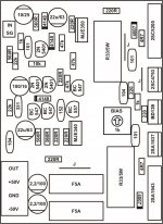
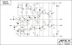
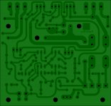
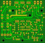
Post the exactly shematic and pcb used.
Corrected schematic/component layout
Roger that.
Please note that I take no credit whatsoever for the posted schematic/component layout. apexaudio is the author and it his his hard work - the only thing I did was reversing the polarity of the aforementioned 1N4007.
The PCB used is just the original 🙂
Ok that's is good!
Post the exactly shematic and pcb used.
Roger that.
Please note that I take no credit whatsoever for the posted schematic/component layout. apexaudio is the author and it his his hard work - the only thing I did was reversing the polarity of the aforementioned 1N4007.
The PCB used is just the original 🙂
Attachments
Last edited by a moderator:
Roger that.
Please note that I take no credit whatsoever for the posted schematic/component layout. apexaudio is the author and it his his hard work - the only thing I did was reversing the polarity of the aforementioned 1N4007.
The PCB used is just the original 🙂
mister Miles did fix it in post #253 so that means you did a good troubleshooting 🙂 atention to details that is good 😀
Regards
Juan
Last edited:
mister Miles did fix it in post #253 so that means you did a good troubleshooting 🙂 atention to details that is good 😀
Regards
Juan
Ha, good point! Thought of reading all 324 pages, but...

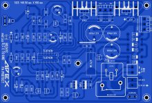
Is normal man, sometimes we don't see errors till we check many times, I keep working with layout and sometimes I made small mistakes it happens that is why I like it and it keep my mind occupied and learning more every day here is an example, I did this layout a few months ago and I still checking for erratas ones I see is all good then I saved it for later. 😉
Juan
Juan
Attachments
Last edited:
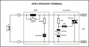
Hello guys 😀
I'm organizing my future projects and I was coping the protect layout with the triac
quick question ...🙂
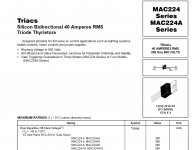
what voltage triac is use on this circuit ? 😕 options are:
200V to 800V
Regards
Juan
I'm organizing my future projects and I was coping the protect layout with the triac
quick question ...🙂
what voltage triac is use on this circuit ? 😕 options are:
200V to 800V
Regards
Juan
Attachments
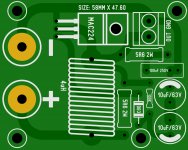
Hello guys 😀
I'm organizing my future projects and I was coping the protect layout with the triac
quick question ...🙂
what voltage triac is use on this circuit ? 😕 options are:
200V to 800V
Regards
Juan
Nice curve trace in sprint layout...😉
- Home
- Amplifiers
- Solid State
- 100W Ultimate Fidelity Amplifier