I also tried to parallel the 1468... and got same results you did. I thought at the time... IIRC.... that it was dc offsets that caused the heating up ... maybe they were trying to sink/source the dc offset preventing direct parallel use in the oscillator role for the HP339A. I'll have to find the Bob P offset equalizing method.
When I get back to my lab in California I am going to try a lot of IC's to see which can be directly paralleled and which need some small additional fix to make them useable in parallel.
But dont wait for me....
THx-RNMarsh
snoa862.pdf
Just google this. I'd send it to you but I don't know if can get it where you are.
The offset of the 1468 is few hundred uV. It's a very fast op amp. Directly paralleling them might cause them to fight. Then they won't settle.
I found new amp at AD. The ADA4870. It can do 1A. It's a CFA and I dropped directly into JCX's sim. The Bandwidth is lower and so is the gain but it works.
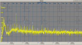
TPA6120 measurements
Here are a couple of measurements. More soon. . .
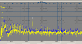
This is running 15 v supplies. The input Z in 1K and its running inverted. First no load second, 50 Ohm load. The second harmonic is the only offender really. If I can graft an opamp around it using the proposed circuit it will be interesting to see where I end up. I will explore dead-buging it over some ground plane.
Here are a couple of measurements. More soon. . .
This is running 15 v supplies. The input Z in 1K and its running inverted. First no load second, 50 Ohm load. The second harmonic is the only offender really. If I can graft an opamp around it using the proposed circuit it will be interesting to see where I end up. I will explore dead-buging it over some ground plane.
Attachments
Here are a couple of measurements. More soon...
Thanks--what level? For the application under discussion I'd check with +20 dBu.
Samuel
Right now, with the 1K input and unity gain my lowest distortion source will only get around 2V out and it still has the 10 Ohm series output resistor. I need to so some more surgery to get it right. There are zero ohm resistors to ground on all the inputs and there is no solder relief on the pads so its not quick to reconfigure.
I think the second harmonic is actually better than shown. The 725D still is a little high on that harmonic. Not sure why. The older 725 seems to be better on this right now.
If it responds to the dual loop things will look pretty good.
I think the second harmonic is actually better than shown. The 725D still is a little high on that harmonic. Not sure why. The older 725 seems to be better on this right now.
If it responds to the dual loop things will look pretty good.
Thanks--what level? For the application under discussion I'd check with +20 dBu.
Samuel
Hi Samuel,
Glad to meet you here^_^
I got a amplifier topology which diliver unmeasurable distortion. But I got only ATS-2 in hand.
maybe you know the ATS system from AP does not include Notch filter before ADC and DSP create FFT, so the THD I can measure from ATS-2 just produced by the test equipment itself.
I tried to setup a external Notch filter using breadboard, but the noise floor is too high for capture harmonics.
So, I am looking for a good notch filter now. Do you mind to give me your comment or some aggestions?
Thank you in advance.
BR
Paul Lu
audio frequency "reactive loads" are seldom a problem in audio amp performance - if the amp can drive the needed I into a R then it usually can drive a L or C to the same current - power dissipation does change and has to be looked at
in most amp's the distortion performance is dominated by the output stage - in this situation really distortion is mostly correlated with the current load - doesn't change much with the phase angle
the feedback capacitor in an integrator doesn't count a "reactive load" at stability frequencies
in most amp's the distortion performance is dominated by the output stage - in this situation really distortion is mostly correlated with the current load - doesn't change much with the phase angle
the feedback capacitor in an integrator doesn't count a "reactive load" at stability frequencies
Last edited:
Hello,
If you don't mind discreets what about Bob C's power amplifier with a composite opamp input? That would give you an output capability of driving 10 ohms with 20Vrms.
If you don't mind discreets what about Bob C's power amplifier with a composite opamp input? That would give you an output capability of driving 10 ohms with 20Vrms.
I think the second harmonic is actually better than shown. The 725D still is a little high on that harmonic. Not sure why. The older 725 seems to be better on this right now.
.
The 2H shown on the 725D is about same as AP2722, as I recall.
-RM
I got a amplifier topology which diliver unmeasurable distortion. But I got only ATS-2 in hand. maybe you know the ATS system from AP does not include Notch filter before ADC and DSP create FFT, so the THD I can measure from ATS-2 just produced by the test equipment itself. I tried to setup a external Notch filter using breadboard, but the noise floor is too high for capture harmonics.
So, I am looking for a good notch filter now. Do you mind to give me your comment or some aggestions?
There's no easy answer to this. At what frequencies and levels do you want to do your measurements? What is the expected distortion of the DUT, or the needed distortion residual of the test set? Note that you don't just need a good notch filter, the generator needs to keep up as well.
Did you use a passive notch filter? Possibly a good preamplifier after it might solve the noise issue.
For amplifiers with flat frequency response it is also possible to enhance the measurement resolution by looking at the input-output difference signal of the DUT (google Cordell distortion magnifier).
Samuel
If you don't mind discreets what about Bob C's power amplifier with a composite opamp input? That would give you an output capability of driving 10 Ohms with 20 Vrms.
Perhaps, but what's the point of having so much output current capability? The output amplifiers I'm using drive +24 dBu at about ~150 mA peak, with an EIN of 1.1 nV/rtHz. That's enough for extremely good performance (very low THD and THD+N over all output levels, attenuator with 50 Ohm output Z). If +20 dBu output level and an attenuator with 100 Ohm output impedance is enough, the drive capability of an ordinary monolithic opamp is enough.
Samuel
In light of the output requirements can we meet them with the opamp+buffer using the LME49600 or LT1010? The overall open loop gain is less but still lots and the devices are pretty free of problems before feedback.
Sent from my MyTouch 4G Slide using Tapatalk
Sent from my MyTouch 4G Slide using Tapatalk
49610 is a little bit better on a high signal levels.with the opamp+buffer using the LME49600
I don't find either of the LME49600/10 all that compelling when you look at the datasheet - how is 10 dB 100 MHz peaking pretty free of problems?
the distortion of the buffer itself isn't speced, only inside another op amp loop
the "stable with any Cload" is from having the output series resistance built in to the supply chip - and not speced on the DS either
the AD8397 is a VFA just capable of +20dBu 50 Ohm drive but has 24V(+/-12) max rating and "only" 69 MHz GBW
I have used this chip - and it does blow up - the thermal protection isn't fast enough for some conditions
My point was that the buffers are linear with current gain and little crossover distortion. Inside a loop with an opamp rolling off before the 100 MHz peak it should be trouble free. A compound opamp is not as simple to make work. If the simple meets the requirements why go further? Its easy here to confuse audiophile with measurement requirements.
Sent from my Nexus 7 using Tapatalk
Sent from my Nexus 7 using Tapatalk
12v supply won't get to 10v RMS. 20 dBu is different from 20 dBV. Other than that its a good solution.
Is 3V enough? It will drive any power amp to clipping. I want more but not for good reason.
Sent from my Nexus 7 using Tapatalk
Is 3V enough? It will drive any power amp to clipping. I want more but not for good reason.
Sent from my Nexus 7 using Tapatalk
maybe you need a bigger display?
I think that comment is just something like the email do display "sent from Paul's iPhone' in most of the default software setting ^_^
Never mind, to my opinion.
BR
Paul
- Home
- Design & Build
- Equipment & Tools
- Low-distortion Audio-range Oscillator