No. But they assume that the reader is 'skilled in the art' to put that statement into proper context of his application...So in other words when they state thatthey're wrong?The LM3886 is designed to be stable when operated at a closed-loop gain of 10 or greater
Sure. I can run that sim for you...
The TI model for the LM3886 is OK, their models for the LME49830 etc leave a lot to be desired.
TI uses TINA freeware version and you can do the AC analysis in a snap.
now i was curious.......
had no lm3886 on hand, so i used a lm1875.
feed back network was 20k/1,2k + 10uF.
no input cap.
tested the 1875 with very low frequencies from a signal generator (sinus,triangle,rectangular).
seems to work........
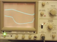
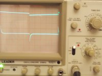
here an example foto of a 7Hz signal:
upper curve = input
lower shows output (amp load was a full range speaker 4ohm).
had no lm3886 on hand, so i used a lm1875.
feed back network was 20k/1,2k + 10uF.
no input cap.
tested the 1875 with very low frequencies from a signal generator (sinus,triangle,rectangular).
seems to work........
here an example foto of a 7Hz signal:
upper curve = input
lower shows output (amp load was a full range speaker 4ohm).
Attachments
Last edited:
Hi mjf,
It's looking like my assumptions on this matter may have been wrong. (I hate being wrong) But I was wondering if you would mind trying the same test but with a much smaller cap instead of the 10uF, maybe something like 1uF? I'm just curious, and right now I have too many other things going on to try it myself.
Mike
No. But they assume that the reader is 'skilled in the art' to put that statement into proper context of his application...
Well put.
~Tom
Six hours of simulations and documentation later...
Inspired by all this chatter about the "stability issues" surrounding the LM3886, I've been meaning to type up a white paper or website on the topic. It looks like I have the majority of the simulation work done. Here's a preview:
First a note on stability analysis using a circuit simulator. Textbooks make it sound so simple. Just disconnect the feedback and insert a test voltage source... Sounds simple until you try it in the lab or simulator. In order for the DC operating point to be calculated correctly by the circuit simulator, the loop needs to be closed (connected) at DC. But for the AC part of the simulation, the loop needs to be open. There are a few ways of doing this - the most common one is to use an LC filter with an extremely low cutoff frequency. I used L = 10 MH and C = 1 MF. That's capital M as in Mega... This puts the cutoff at 16 uHz. Low enough to ensure that the loop is open for the frequencies we're interested in (1 Hz and up). This allows the loop gain to be simulated. Recall from earlier:
Forward gain, A = raw gain of op-amp (115 dB at DC in case of the LM3886).
Feedback gain, beta = gain of the feedback network. In audio amps, the feedback network is attenuating, hence, beta is below 1.
Loop gain = A * beta
Closed loop gain = gain from the input to the output of the amp when feedback is applied. Acl = A/(1+A*beta). This can be approximated as Acl = 1/beta for large values of A.
Note that the test signal is injected via C1 (= 10 MF) into the inverting input of the LM3886, hence, 180 degrees should be subtracted from the phase read on the output if the loop phase is of interest. Another way to look at this is that the phase curve represents the phase margin. The PM is really what we're after, so life's good...
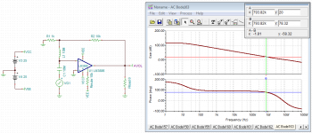
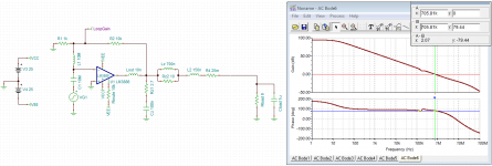
Let's first verify the model. See the AVOL graph in the data sheet and compare with the first image attached. The model shows the 115 dB open loop gain and a unity gain bandwidth of about 10.5 MHz. I've placed a marker where the AVOL crosses 20 dB and placed a second marker on the phase curve at the frequency where the AVOL crosses 20 dB. The resulting phase reading would be the phase margin we'd get if we were to configure the LM3886 for a gain of 20 dB. Compare with my analysis from yesterday and you'll notice that the PM in simulation is a bit optimistic. The UGBW is also a bit higher than the data sheet numbers.
The data sheet graph is measured data, so it will include some layout parasitics. The model is likely derived from simulated data. That may be the reason there's a slight discrepancy between the two. Basically, this is the constant reminder to verify circuit performance in the lab once built...
In order for a control system to be stable, two criteria must both be satisfied:
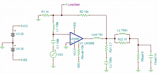
The second image shows the simulation schematic. I am trying to explore these two configurations:
For all simulations, the closed loop gain was 20 dB (-10 V/V in inverting configuration, +11 V/V for non-inverting). I.e. R1 = 1 kOhm, R2 = 10 kOhm. The load resistor, Rload was kept at 8 ohm. Cload was varied from ~0 to 10 uF as follows: 1 fF, 1 nF, 2 nF, 5 nF, 10 nF, 20 nF, 50 nF, 100 nF, 200 nF, 500 nF, 1 uF, 2 uF, 5 uF, 10 uF. 1 fF (= 0.001 pF) was used in lieu of zero as zero cannot be plotted on a logarithmic axis.
First let's look at the impact of the layout. It's mentioned explicitly in the data sheet that the inductance in the path from the output pin to the inverting input of the LM3886 must be minimized for best stability. The best layout would have the feedback resistor parallel to the LM3886 and short traces to the pins. I figure a reasonably tight layout would probably result in a path length of about 10 mm. Figure 1 nH/mm and you have 10 nH in the feedback path. I model this as Lout.
Now, let's rotate the resistor 90º so it's now perpendicular to the LM3886. This results in a longer routing path. Even if the traces are kept pretty short, I figure a total path length of 30 mm --> Lout = 30 nH to be reasonable.
The impact of the layout is pretty stark and shown in image #3. I have included the ideal case where Lout = 0 nH. Note how the PM takes a nose dive when Cout exceeds 100 nF in the case of the poor layout, whereas the amp with the good, tight layout is technically stable even at 10 uF load cap. Now, personally I would not push this circuit much past Cload = 1 uF as both the PM and GM indicate questionable performance with this much capacitance.
Now, let's see what this here Zobel network does (image #4). It should be pretty clear to everybody that the Zobel network is your friend.
Now, Cload and Lout do engage in a pretty nasty resonance that almost kills the PM once Cload exceeds a few uF, so I would not recommend using the LM3886 to drive 10 uF even with a Zobel network attached. I will explore this in greater depth on my website once I type it all up.
~Tom
Can anyone confirm what happens to the phase margin when small values of capacitance (1nF to 100nF) due to output cables, speaker crossovers and reactive speaker drive units are added to the resistive load?
Inspired by all this chatter about the "stability issues" surrounding the LM3886, I've been meaning to type up a white paper or website on the topic. It looks like I have the majority of the simulation work done. Here's a preview:
First a note on stability analysis using a circuit simulator. Textbooks make it sound so simple. Just disconnect the feedback and insert a test voltage source... Sounds simple until you try it in the lab or simulator. In order for the DC operating point to be calculated correctly by the circuit simulator, the loop needs to be closed (connected) at DC. But for the AC part of the simulation, the loop needs to be open. There are a few ways of doing this - the most common one is to use an LC filter with an extremely low cutoff frequency. I used L = 10 MH and C = 1 MF. That's capital M as in Mega... This puts the cutoff at 16 uHz. Low enough to ensure that the loop is open for the frequencies we're interested in (1 Hz and up). This allows the loop gain to be simulated. Recall from earlier:
Forward gain, A = raw gain of op-amp (115 dB at DC in case of the LM3886).
Feedback gain, beta = gain of the feedback network. In audio amps, the feedback network is attenuating, hence, beta is below 1.
Loop gain = A * beta
Closed loop gain = gain from the input to the output of the amp when feedback is applied. Acl = A/(1+A*beta). This can be approximated as Acl = 1/beta for large values of A.
Note that the test signal is injected via C1 (= 10 MF) into the inverting input of the LM3886, hence, 180 degrees should be subtracted from the phase read on the output if the loop phase is of interest. Another way to look at this is that the phase curve represents the phase margin. The PM is really what we're after, so life's good...
Let's first verify the model. See the AVOL graph in the data sheet and compare with the first image attached. The model shows the 115 dB open loop gain and a unity gain bandwidth of about 10.5 MHz. I've placed a marker where the AVOL crosses 20 dB and placed a second marker on the phase curve at the frequency where the AVOL crosses 20 dB. The resulting phase reading would be the phase margin we'd get if we were to configure the LM3886 for a gain of 20 dB. Compare with my analysis from yesterday and you'll notice that the PM in simulation is a bit optimistic. The UGBW is also a bit higher than the data sheet numbers.
The data sheet graph is measured data, so it will include some layout parasitics. The model is likely derived from simulated data. That may be the reason there's a slight discrepancy between the two. Basically, this is the constant reminder to verify circuit performance in the lab once built...
In order for a control system to be stable, two criteria must both be satisfied:
- The system must have sufficient phase margin (PM). The textbook definition of "sufficient" is generally 45º. I normally design for at least 60º, and as we discussed yesterday, if the system should be optimized for low overshoot in the step response, an even higher PM is desirable. PM < 0º is unstable. PM < 45~60º is not technically unstable, but not useful for audio (or much of anything else other than oscillators).
- The system must have sufficient gain margin (GM). I aim for at least -10 dB of gain margin. Lower is better. I.e. GM = -20 dB is better than GM = -10 dB. GM = 0 dB < unstable.
The second image shows the simulation schematic. I am trying to explore these two configurations:
- Impact of poor layout on stability.
- Impact on the use of a Zobel network on stability.
For all simulations, the closed loop gain was 20 dB (-10 V/V in inverting configuration, +11 V/V for non-inverting). I.e. R1 = 1 kOhm, R2 = 10 kOhm. The load resistor, Rload was kept at 8 ohm. Cload was varied from ~0 to 10 uF as follows: 1 fF, 1 nF, 2 nF, 5 nF, 10 nF, 20 nF, 50 nF, 100 nF, 200 nF, 500 nF, 1 uF, 2 uF, 5 uF, 10 uF. 1 fF (= 0.001 pF) was used in lieu of zero as zero cannot be plotted on a logarithmic axis.
First let's look at the impact of the layout. It's mentioned explicitly in the data sheet that the inductance in the path from the output pin to the inverting input of the LM3886 must be minimized for best stability. The best layout would have the feedback resistor parallel to the LM3886 and short traces to the pins. I figure a reasonably tight layout would probably result in a path length of about 10 mm. Figure 1 nH/mm and you have 10 nH in the feedback path. I model this as Lout.
Now, let's rotate the resistor 90º so it's now perpendicular to the LM3886. This results in a longer routing path. Even if the traces are kept pretty short, I figure a total path length of 30 mm --> Lout = 30 nH to be reasonable.
The impact of the layout is pretty stark and shown in image #3. I have included the ideal case where Lout = 0 nH. Note how the PM takes a nose dive when Cout exceeds 100 nF in the case of the poor layout, whereas the amp with the good, tight layout is technically stable even at 10 uF load cap. Now, personally I would not push this circuit much past Cload = 1 uF as both the PM and GM indicate questionable performance with this much capacitance.
Now, let's see what this here Zobel network does (image #4). It should be pretty clear to everybody that the Zobel network is your friend.
Now, Cload and Lout do engage in a pretty nasty resonance that almost kills the PM once Cload exceeds a few uF, so I would not recommend using the LM3886 to drive 10 uF even with a Zobel network attached. I will explore this in greater depth on my website once I type it all up.
~Tom
Attachments

Now let's throw a wrench in the works and watch the sparks fly... 🙂
I took a look at the circuit shown in the Test Circuit #2 (AC Test) in the data sheet. I notice a lot of circuits that have a capacitor across the input of the amp and an extra RC in the feedback path.
I used Rload = 8 ohm, not the 2 kOhm shown in the data sheet as we're using these LM3886es to drive speakers, not 2 kOhm resistors...
I then ran a simulation where I removed the "optional stability components", Cc, Rf2, and Cf.
The performance is considerably worse with these "optional stability components" added... I think Cc is used to deal with the circuit response when the SPiKe protection engages or the output reaches clipping. One may get considerably better PM by decreasing Cc to 100 pF (not shown).
I think that's enough computer time for me today... 🙂 Enjoy.
~Tom
Attachments


Last edited:
I would bin the original circuit and PCB - start from a blank sheet of paper
it is possible for "lead-lag" compensation to help but those are the wrong values and the C across the inputs is just plain wrong period
"noise gain" compensation can make for improved stabilty margins if you really want lower Av
EE types ussually have the freedom of large GBW, can use feedback to both meet stability/performance requirements and hit a particular gain curve/dynamic response
but in general control theory the 2 goals are separated - use feedback for sensitivity/distortion/output Z reduction within stability limits - and then pre-filter to control step response/overshoot if required
Last edited:
Thanks.
I have just skimmed through the attached pics.
I will come back and read the whole report thoroughly. It deserves that.
I have just skimmed through the attached pics.
I will come back and read the whole report thoroughly. It deserves that.
I will come back and read the whole report thoroughly. It deserves that.
Thanks. I appreciate it. I'll post a note when I get my write-up up on my website as well. It'll have more detail and some gain/phase plots to show more detail.
~Tom
it is possible for "lead-lag" compensation to help but those are the wrong values and the C across the inputs is just plain wrong period
I agree. But that's what's used in the data sheet... Bob Cordell uses the same components. As does Peavey (guitar amp manufacturer) except they use 180 pF for Cc. That others are using those components doesn't make it right, though.
I still don't think Cc, Rfb2 and Cfb help on stability. My simulations state that quite clearly. I've never been a fan of caps across op-amp inputs either.
~Tom
The Cc cap should be disconnected from the -IN Pin and connected to the Signal Ground.
The Cf should be sized by results from thorough testing for stability of the completed amplifier. Then Rf2 needs optimising after a near enough Cf has been determined. This test and adjust loop for Cf Rf2 may have to be traversed more than a couple of times.
This "completed" amp must contain the Thiele Output Network. Post67 shows it as omitted.
What happens if a little parasitic resistance is added to the 10nH on the output?
Is there a critical minimum resistance that cancels most/some of the bad effects of the 10nH?
What happens if a second output Zobel is added at the speaker terminals, thus creating a Pi version of the Thiele Network?
Cordell has commented on this in his book. I have a feeling that was added after he got involved in this Forums "interviews".
Any explanation as to why the LM3886 is so much more practical when used as an inverting amplifier?
It's not about "practicality", it's because applying the audio signal to the inverting input of an op-amp eliminates common-mode distortion. See here: http://www.diyaudio.com/forums/solid-state/6558-opamp-inverting-input-sounds-better.htmlAny explanation as to why the LM3886 is so much more practical when used as an inverting amplifier?
Common-mode distortion in non-inverting configurations can be controlled by matching the impedance at both the inverting and non-inverting inputs (not an easy thing to do), or by keeping the driving impedance to the inputs low, generally in the very low K-ohms range or even lower.
Mike
Hi mjf,
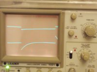
But I was wondering if you would mind trying the same test but with a much smaller cap instead of the 10uF, maybe something like 1uF?
Mike
now feedback cap = 1uF ( so -3db at 130Hz)
an example foto with 10Hz........
listend to music with it (jbl control one).....seems to work.
Attachments

Last edited:
The Cc cap should be disconnected from the -IN Pin and connected to the Signal Ground.
The Cf should be sized by results from thorough testing for stability of the completed amplifier. Then Rf2 needs optimising after a near enough Cf has been determined. This test and adjust loop for Cf Rf2 may have to be traversed more than a couple of times.
This "completed" amp must contain the Thiele Output Network. Post67 shows it as omitted.
I used the components used by National Semiconductor on the LM3886 load board used in the AC test. I don't claim that they are optimized. I have on different occasions tried to optimize these components. I did not observe any significant effect of messing with Rf2 and Cf. There is an effect, but I would not call it significant. You may be able to affect the PM by a few degrees. The biggest impact is that Rf2 and Cf increase the bandwidth of the amp. That may result in improved performance at high frequencies. I don't see any effects in the audio band, though. The zero-pole pair formed in the loop response by Rf2 and Cf are in the mid 100s kHz.
Decreasing Cc does have a significant effect. Decreasing Cc improves PM considerably.
I really don't think Rf2, Cf2, and Cc are such a hot idea. At least not from a small signal stability point of view.
You say the amp "must include a Thiele network". I'm assuming you mean the L||R on the output. That is included in the simulation. See the second image on Post #67. I also included the Zobel network (not used in the test circuit by NSC). See image #1 to this post. Sorry for not making that clear earlier.
What happens if a little parasitic resistance is added to the 10nH on the output?
Is there a critical minimum resistance that cancels most/some of the bad effects of the 10nH?
Any series resistance with Lout would dampen the resonance formed by Lout and Cload. But so does Rload. If you were to add, say, 10 ohm in series with Lout, you could probably get some stability improvement, but the amp wouldn't be able to source much current, hence, would be useless for audio purposes. I don't think you can add enough resistance there to make a meaningful difference.
Any parasitic resistance in series with Lout will likely be swamped by the output impedance of the LM3886. That's in series with Lout as well...
What happens if a second output Zobel is added at the speaker terminals, thus creating a Pi version of the Thiele Network?
I doubt a second Zobel will have much, if any, impact. I'm sure TINA will be able to answer that question. Stay tuned.
~Tom
Attachments
So here's my thinking:
If the R||L network was not there, a dual Zobel network would have no effect. Basically, the dual Zobel - in that case - could be reduced to a network of 2*C + R/2. This places a zero at the exact same frequency as C+R. I suspected the impact of L||R would be minimal, hence, I suspected the dual Zobel to have little to no effect.
TINA confirms this...
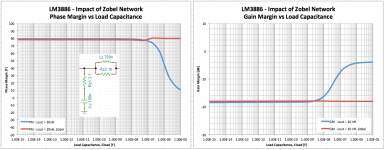
First image compares PM and GM for single vs dual Zobel networks. I included 15 cm of heavy gauge wire (150 nH + 25 mΩ) to model the effect of placing the second Zobel at the speaker output terminals.
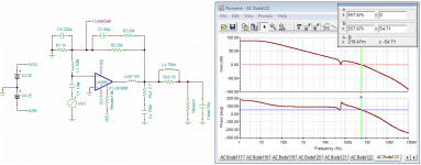
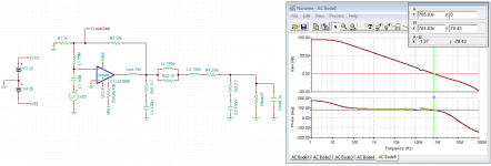
Second image shows the loop gain with PM marked for the dual Zobel case. Third image shows what happens if the second Zobel is removed. You'll barely be able to tell a difference between the two responses unless you flip back and forth between the two images.
I have attached the TINA simulation file as well. If you have further "what if" or "what would be the effect of..." types of questions, feel free to play with it in TINA. TINA-TI can be downloaded here: TINA-TI Spice Simulator. It's free...
DIY Audio would not accept TINA's file extension of .TSC so I added .txt. To use the TINA circuit file, remove the .txt. The file name should be: LM3886-LoopStability.TSC
~Tom
If the R||L network was not there, a dual Zobel network would have no effect. Basically, the dual Zobel - in that case - could be reduced to a network of 2*C + R/2. This places a zero at the exact same frequency as C+R. I suspected the impact of L||R would be minimal, hence, I suspected the dual Zobel to have little to no effect.
TINA confirms this...
First image compares PM and GM for single vs dual Zobel networks. I included 15 cm of heavy gauge wire (150 nH + 25 mΩ) to model the effect of placing the second Zobel at the speaker output terminals.
Second image shows the loop gain with PM marked for the dual Zobel case. Third image shows what happens if the second Zobel is removed. You'll barely be able to tell a difference between the two responses unless you flip back and forth between the two images.
I have attached the TINA simulation file as well. If you have further "what if" or "what would be the effect of..." types of questions, feel free to play with it in TINA. TINA-TI can be downloaded here: TINA-TI Spice Simulator. It's free...
DIY Audio would not accept TINA's file extension of .TSC so I added .txt. To use the TINA circuit file, remove the .txt. The file name should be: LM3886-LoopStability.TSC
~Tom
Attachments

theory smeary, now you drove off the OP (just kidding some good stuff from tomchr). so what about the OPs question? IE the earlier generation part was great now that I've upgraded it's dead sounding!
His schematic doesn't seem to go in hand with what I can see on his hardware image, ( he deleted it a couple of days ago ) what was it modded from something else? maybe someone simply goofed, maybe Cin is the wrong value by a factor of 100, an example Ive seen done here! I think he should run a few tests, gain and frequency flatness IE 3 dB points, perhaps max power into a dummy load ( heatsink and PS integrity), extra credit a 1V square wave test into his speaker for stability. That would be my suggestion.
carry on
Last edited:
- Status
- Not open for further replies.
- Home
- Amplifiers
- Chip Amps
- Improving the LM3886 amplifier