The sound has improved a little .. but still dark sound signature.Yes.
When fixing this kind of thing, just change one thing at a time and test it. Be methodical.
Move the 220pF cap and see how it changes the sound. It will probably be fine after you do that.
Afterwards removed 50pF that connected in series with 20Kohm feedback resistor.
Caused sound to be less balanced, so returned them.
Maybe it's the sound signature of sound of this component?
sometimes i ask myself: is the lm3886 unity gain stable?
NO, it's internal compensation makes it stable only for gains of ten or greater.
Mike
Look at the phase and gain margins when Closed Loop gain is set to that minimum of 10. Not nice.
Better to use CLgain between 20 and 40 for better margins.
Look also at overshoot when set to lowish CLgains.
Based on listening tests, many builders report a gain setting of 26 to 28times as "sounding" nice.
Better to use CLgain between 20 and 40 for better margins.
Look also at overshoot when set to lowish CLgains.
Based on listening tests, many builders report a gain setting of 26 to 28times as "sounding" nice.
Ci Feedback capacitor. Ensures unity gain at DC. Also a low frequency pole (highpass roll-off) at:
fc = 1/(2πRi Ci)
fc = 1/(2x3.14x1000x0.000010) = 15,9Hz
I think I got this right.
fc = 1/(2πRi Ci)
fc = 1/(2x3.14x1000x0.000010) = 15,9Hz
I think I got this right.
I respectfully disagree. Here's why. You mention that the chip has 115dB gain at DC, but I was talking about what happens to the amp's gain BELOW Fs on the feedback network where the amp's gain begins to fall off toward unity. For example, let's say you have a Lm3886 configured for DC coupling at the input and AC coupling with a Fc of 100Hz on the feedback network while running a gain of 10 for the pass band (an extreme case just to illustrate my point). What would happen if you applied a 20Hz signal to the input? At that frequency the gain would fall toward unity and the amp would be operating in an unstable conditon. So doesn't it seem appropriate to design the circuit in such a way to minimize the possability of causing the issue to begin with, especially since the fix is cheap and easy; just make the cap on the feedback network bigger.
Mike
To make the math easier, I will use a 10 Hz signal.
If the amp has a gain of +10 V/V with Fc = 100 Hz, then the pole and zero I talked about in Post #39 are located as follows:
Fz = 1/(2*pi*(R1+R3)*C1) = 10 Hz
Fp = Fc = 1/(2*pi*R1*C1) = 100 Hz
This means the amp will have 10 V/V (= 20 dB) of gain mid band and 1 V/V (= 0 dB) gain at DC with a transition at +20 dB/dec from 10 Hz to 100 Hz. At 10 Hz (Fz) the gain should be about 3 dB (= 1.414 V/V) and at 100 Hz, it should be 17 dB (= 20 - 3 dB or 7.08 V/V).
This also means that if you apply a 1 V amplitude test signal at 10 Hz, you should get 1.414*1 = 1.414 V out of the amplifier. My simulations confirm this.
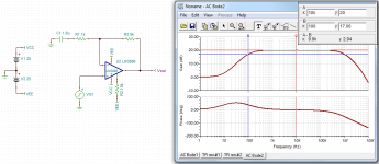
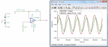
See my simulation results below. The first image shows the frequency response (gain) of the amplifier. You can clearly see the 0 dB gain at LF, transition from 0 dB to 20 dB at a 20 dB/dec slope from Fz to Fp and 20 dB midband. The roll-off at HF is caused by the limited bandwidth of the LM3886 itself. The second image shows the transient response with a 10 Hz sine wave input. This is what you would see if you were to measure the circuit with an oscilloscope.
Note that in simulator terms, "transient" means that time is the swept variable. "AC" means the frequency is swept.
~Tom
Attachments
Look at the phase and gain margins when Closed Loop gain is set to that minimum of 10. Not nice.
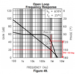
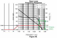
The datasheet indicates that the PM should be greater than 60 deg at a closed loop gain of 10 (= 20 dB). See attached. The figure is straight from the LM3886 datasheet. I annotated it to show the PM at a closed loop gain of 20 dB.
Look also at overshoot when set to lowish CLgains.
Always measure the transient response of the amp. I agree wholeheartedly there. In the ideal world, we would also measure the loop gain and confirm the phase margin, but few people have the gear necessary for this. Although, the measurement is really not that difficult.
Alternatively, one can measure the output impedance (versus frequency) of the amp. That says a lot about stability as well.
~Tom
Attachments
OK, this is straight from the data sheet:
Mike
You said:The LM3886 is designed to be stable when operated at a closed-loop gain of 10 or greater, but as with any other high-current amplifier, the LM3886 can be made to oscillate under certain conditions. These usually involve printed circuit board layout or output/input coupling.
Now do you see the problem? By the way, how well do your simulations show circuit instability?This means the amp will have 10 V/V (= 20 dB) of gain mid band and 1 V/V (= 0 dB) gain at DC with a transition at +20 dB/dec from 10 Hz to 100 Hz. At 10 Hz (Fz) the gain should be about 3 dB (= 1.414 V/V) and at 100 Hz, it should be 17 dB (= 20 - 3 dB or 7.08 V/V).
Mike
To be exact, the problem zone is only at the intercept of open-loop gain and feedback factor 1/ß (where loop gain is unity) and the second condition for oscillation is that the phase response of the two is 180 deg apart (while absolute slope is not important).Instability is caused when the phase angle through the amplifier and the feedback network to the inverting input is greater than 180 º as this will cause positive feedback. If the loop gain (gain of the amp and the feedback network combined) is greater than 1 V/V when the phase hits -180º, the amp will oscillate.
There is a key heading in a legendary BB app note by Gerald Graeme which goes 'phase only matters at the intercept' (actually there can be two intercepts, one at HF and one close to DC if you have a servo loop installed -- both can be treated the same way). It took me years to really understand it, now that I have I can design higher-order feedback topologies as well as higher order servos systematically by close examination of simulated or measure bode plots showing Aol and 1/ß.
http://www.ti.com/general/docs/lit/getliterature.tsp?baseLiteratureNumber=SBOA015&fileType=pdf
In a controlled environment (say, active speaker) LM3886 is perfectly stable at a noise gain of 10x that must be fully established for a decade below the intercept (so, from about 20kHz bascially).
OK, this is straight from the data sheet:
The LM3886 is designed to be stable when operated at a closed-loop gain of 10 or greater, but as with any other high-current amplifier, the LM3886 can be made to oscillate under certain conditions. These usually involve printed circuit board layout or output/input coupling.
You said:
Now do you see the problem? By the way, how well do your simulations show circuit instability?
I maintain that there is no stability problem by feeding a signal below Fc into the amp. That's what we are discussing, right?
Now about the blurb from the data sheet: Of course you can get any high-current, high power opamp to oscillate under certain conditions. HF instability would be one of those conditions. This condition occurs when the amp runs out of phase margin due to
- Crappy engineering
- Excessive capacitive load
- Excessive parasitic inductance in the feedback network (crappy layout)
- Lack of supply decoupling (see crappy engineering)
- Low phase margin (see crappy engineering)
LF oscillation, such as motor-boating, happen when the amplifier browns out on a transient due to crappy power supply engineering or crappy ground routing.
None of these have anything to do with the signal input to the amp. In fact, these types of instability will create an amplifier output even without an input.
As the previous poster pointed out, instability can happen when the loop gain crosses 1 V/V (0 dB). The loop phase at this point must be at least -180 + PM degrees, where PM is the phase margin. As the previous poster also points out, this can happen at LF, however, in the circuit we are discussing, it does not happen. The loop gain is 115 dB from DC to fz. It does not cross 0 dB until around 1 MHz. There is NO loop stability issue at LF with an LM3886.
All semiconductors manufactured since the mid/late 1970ies (perhaps even earlier) have been designed using computer simulation. I happen to do this for a living (my resume is available on my website if you're interested in my background). With good models, the performance of the actual circuit is actually very, very close to the simulated performance. Of course, if you feed garbage into the simulator, you'll get garbage results... That said, the LM3886 model available for download on TI's website seems to match the datasheet pretty accurately. It may be a tad optimistic on the bandwidth, but I'll trust it for stability simulations.
Loop stability can be a bit difficult to grasp at first, but for those interested in the knowledge, I suggest:
Sergio Franco, "Design with Operational Amplifiers and Analog Integrated Circuits". Chapter 8 covers stability. The 4th edition is the current one. A 2nd or 3rd edition would work just as well and may be available for less.
Sedra & Smith, "Microelectronic Circuits". It looks like the current edition is the 6th. I have the 2nd, 3rd, and 5th. Any of those would work, though, I'd probably go with a 3rd edition or above as these include Spice simulation.
If opamp (including chipamp) circuits is your thing, get Franco. If you're curious about what goes into an opamp, get Sedra/Smith.
~Tom
The sound has improved a little .. but still dark sound signature.
Afterwards removed 50pF that connected in series with 20Kohm feedback resistor.
Caused sound to be less balanced, so returned them.
Maybe it's the sound signature of sound of this component?
It's good that you moved the 220pF.
Try replacing the 50pF cap with one of a smaller value, maybe 27pF. This will increase the bandwidth of the amplifier. It can also increase the chance of instability - this will make itself apparent as sharp high frequencies and "lispy" sounding S's when people sing.
Also, try shorting out the 20k resistor in series with the 50pF (R11 on the circuit board) with a piece of wire.
Another thing about this circuit that is less than perfect is the value of the capacitor Ci. Mark Whitney pointed this out in post #31. This capacitor forms a high pass filter with R3 (On the schematic) which dictates the lowest frequencies that the negative feedback can work with. Increase Ci to at least 100uF. This will improve the amplifiers low frequency response.
While I don't expect anyone to go out and purchase equipment; an old cheap oscilloscope would make your life a whole lot easier.
OK, one more time with pictures.
OK, one more time with pictures.


LM3886 amp chip is internally compensated for minimum gain of 20dB (X 10)? Check.
Feedback network has a high pass roll off with -3dB at 100Hz? Check.
Amp has gain of 26dB (X 20) in the pass band? Check.
Amp has gain of 21.5db (X 11.9) at 75Hz? Check, and still within minimum gain requirement.
Amp has gain of 19db (X 8.9) at 50Hz? Uh-oh - not within minimum gain requirement.
Amp has gain of 13.9db (X 4.1) at 25Hz? Uh-oh - REALLY not within minimum gain requirement.
Of course, while nobody would actually build an amp like this, I felt an exaggerated example would illustrate my point better.
And yeah, I get your point that in actual practice having a lower Fc at the input Vs the feedback network doesn't necessarily mean there WILL be problems, the point I'm trying to make is that it makes no sense to build it with the potential to have problems that are easily and simply avoided to begin with. In this case, just make the feedback cap bigger.
Mike
OK, one more time with pictures.
LM3886 amp chip is internally compensated for minimum gain of 20dB (X 10)? Check.
Feedback network has a high pass roll off with -3dB at 100Hz? Check.
Amp has gain of 26dB (X 20) in the pass band? Check.
Amp has gain of 21.5db (X 11.9) at 75Hz? Check, and still within minimum gain requirement.
Amp has gain of 19db (X 8.9) at 50Hz? Uh-oh - not within minimum gain requirement.
Amp has gain of 13.9db (X 4.1) at 25Hz? Uh-oh - REALLY not within minimum gain requirement.
Of course, while nobody would actually build an amp like this, I felt an exaggerated example would illustrate my point better.
And yeah, I get your point that in actual practice having a lower Fc at the input Vs the feedback network doesn't necessarily mean there WILL be problems, the point I'm trying to make is that it makes no sense to build it with the potential to have problems that are easily and simply avoided to begin with. In this case, just make the feedback cap bigger.
Mike
Member
Joined 2009
Paid Member
Just a thought? The low-gain stability is only an issue at high frequencies where the phase margin is too small. At low frequencies, such as in your example, it matters not that the gain is low because the phase margin is still good.
I see the root issue here. You appear to have misunderstood the term "unity gain stable".
"Unity gain stable" means that the amplifier's open loop phase response is higher than -120 degrees when the amplifier's open loop gain crosses 0 dB. This leaves at least 60 degrees of phase margin (PM = -120 - (-180) = 60) when the amplifier is configured as a buffer with no external compensation.
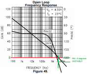
On the first image, I have drawn the case where the LM3886 is wired as a buffer. You will notice the negative PM, hence, the circuit is unstable. The red curve shows 1/(feedback gain). The phase margin and unity loop gain frequency are marked in green.
On the second image, I have drawn the case you simulated. I had to extend the frequency axis to show my point. The red curve shows 1/beta = 1/(feedback gain). The phase margin and unity loop gain frequency are marked in green.
Stability deals with the LOOP GAIN not the CLOSED loop gain. For an LM3886, the closed loop gain can be 0 dB as long as the loop phase hasn't dropped below -120 degrees when the loop gain crosses 0 dB. The CLOSED loop gain is irrelevant for stability analysis. Only the LOOP GAIN (and phase) matters for stability.
Terminology:
Open loop gain (A, forward gain): Raw gain of the op-amp.
Feedback gain (beta): Gain of the feedback network. (usually attenuation, actually, so gain below 1.0 or 0 dB).
Loop gain: [Open loop gain] * [feedback gain] = A*beta.
Closed loop gain: A/(1+A*beta). For large values of A, this simplifies to 1/beta.
I strongly suggest that you read Franco or any of the other references on this. You can also check out this YouTube video on stability analysis using Bode plots.
~Tom
"Unity gain stable" means that the amplifier's open loop phase response is higher than -120 degrees when the amplifier's open loop gain crosses 0 dB. This leaves at least 60 degrees of phase margin (PM = -120 - (-180) = 60) when the amplifier is configured as a buffer with no external compensation.
On the first image, I have drawn the case where the LM3886 is wired as a buffer. You will notice the negative PM, hence, the circuit is unstable. The red curve shows 1/(feedback gain). The phase margin and unity loop gain frequency are marked in green.
On the second image, I have drawn the case you simulated. I had to extend the frequency axis to show my point. The red curve shows 1/beta = 1/(feedback gain). The phase margin and unity loop gain frequency are marked in green.
Stability deals with the LOOP GAIN not the CLOSED loop gain. For an LM3886, the closed loop gain can be 0 dB as long as the loop phase hasn't dropped below -120 degrees when the loop gain crosses 0 dB. The CLOSED loop gain is irrelevant for stability analysis. Only the LOOP GAIN (and phase) matters for stability.
Terminology:
Open loop gain (A, forward gain): Raw gain of the op-amp.
Feedback gain (beta): Gain of the feedback network. (usually attenuation, actually, so gain below 1.0 or 0 dB).
Loop gain: [Open loop gain] * [feedback gain] = A*beta.
Closed loop gain: A/(1+A*beta). For large values of A, this simplifies to 1/beta.
I strongly suggest that you read Franco or any of the other references on this. You can also check out this YouTube video on stability analysis using Bode plots.
~Tom
Attachments
Last edited:
Looks like Bob Cordell's circuit.
Exactly. I've heard it and built it around the LM4780 in parallel. Bob showed it off to our hyper-critical audio society, and all were (seemingly) favorably disposed.
Exactly. I've heard it and built it around the LM4780 in parallel. Bob showed it off to our hyper-critical audio society, and all were (seemingly) favorably disposed.
Cool. I have a sneaky suspicion that he's getting better sound because he's driving the inverting input, hence, avoids most of the common-mode induced distortion. He mentions this in his "Audio Power Amplifiers" book. Within the next couple of weeks I plan to confirm this with a measurement.
~Tom
So in other words when they state that
The LM3886 is not unity gain stable.
Mike
they're wrong?The LM3886 is designed to be stable when operated at a closed-loop gain of 10 or greater
The LM3886 is not unity gain stable.
Mike
Last edited:
60 degrees of phase margin is not universally recognised as the necessary phase margin for good stability.
There seems to be a large body of opinion that states that around 80 degrees and specifically 82 degrees of phase margin is optimal.
Looking at the plots you can see that if the CLgain is set between +26dB and +32dB that the phase margin is of that 80 degree order.
Is it coincidence that this is also the reputed sweet spot for gain in many 3886 chipamp builds?
As is usual for National, just about everything published in the 3886 datasheet refers to purely resistive loading of the output.
Can anyone confirm what happens to the phase margin when small values of capacitance (1nF to 100nF) due to output cables, speaker crossovers and reactive speaker drive units are added to the resistive load?
Last edited:
60 degrees of phase margin is not universally recognised as the necessary phase margin for good stability.
Depends on your criterion for "good stability". For a second order system, one can calculate the overshoot as function of the phase margin. See Table I on This Page.
If you want to be able to reproduce a square wave with no overshoot, you'll want a PM > 75 º.
Technically, all that's required for stability is a positive PM. Of course, you get excessive ringing on the transient response with a lower PM and it exposes you to higher risk of instability caused by higher frequency poles caused by layout parasitics and circuit nonlinearities. Most textbooks use PM > 45 º as the design criterion. I generally design opamps and voltage regulators to have at least 60 º of PM for typical operation, 45 º worst case. If I was designing the control system for a nuclear power plant, I would aim for a higher PM... 🙂
I have not seen any studies of how the PM affects the sound quality. Personal anecdotes are always entertaining, but an actual scientific study would be better. In all fairness, I haven't looked for such a study either. Perhaps someone has a link to one...
There seems to be a large body of opinion that states that around 80 degrees and specifically 82 degrees of phase margin is optimal.
Looking at the plots you can see that if the CLgain is set between +26dB and +32dB that the phase margin is of that 80 degree order.
Is it coincidence that this is also the reputed sweet spot for gain in many 3886 chipamp builds?
It could be a coincidence. I don't have the data to say either way. It could also just be that people are designing for a gain of 26 dB as this is required by the THX standard.
As is usual for National, just about everything published in the 3886 datasheet refers to purely resistive loading of the output.
National had the best data sheets in the industry and was widely recognized for it. Just saying...
Can anyone confirm what happens to the phase margin when small values of capacitance (1nF to 100nF) due to output cables, speaker crossovers and reactive speaker drive units are added to the resistive load?
Sure. I can run that sim for you... I would expect the PM to degrade as a result of the load pole. I'll run it both with and without the Zobel network.
~Tom
Last edited:
if one wants to reproduce a fast transient then overshoot must be avoided, otherwise there is excessive HF content in the reproduced signal.Depends on your criterion for "good stability"..........
.........If you want to be able to reproduce a square wave with no overshoot, you'll want a PM > 75 º..................
There are bound to be some. JLH described a set up method on at least one of his power amps where a VR in an RC compensation was adjusted to square the squarewave because JLH believed that resulted in a more accurate sound reproduction.I have not seen any studies of how the PM affects the sound quality. Personal anecdotes are always entertaining, but an actual scientific study would be better. In all fairness, I haven't looked for such a study either. Perhaps someone has a link to one...
if National hiding true performance behind cold chip temperatures and purely resistive loads is among the best in the IC industry, then that possibly tells us how bad the rest of the industry is at revealing actual performance........National had the best data sheets in the industry and was widely recognized for it. Just saying...
PMI, AD and others are very good at telling us what their ICs can achieve and at telling us what to do to avoid common problems.
Thank you for volunteering.Sure. I can run that sim for you... I would expect the PM to degrade as a result of the load pole. I'll run it both with and without the Zobel network.
......
That will be instructive.
What I can't assess is: when the phase margin reduces with a bit of capacitance on the output, does that impact on the way the amplifier reproduces transients.
Or looking at an alternative compensation:
set up a highish phase margin (minimum distortion of a slow squarewave) with all the amp in it's final form with a full Thiele Network including the second Pi RC to isolate the speaker cables and speaker from affecting the amplifier.
I often wonder if these two ways of setting up what is essentially the same amplifier will impact on the reproduced signal and thus the perceived sound.
Last edited:
- Status
- Not open for further replies.
- Home
- Amplifiers
- Chip Amps
- Improving the LM3886 amplifier