I think the plan is to improve this one. Otherwise he could get two LM3886 kits on EBAY.
If you ask 10 diyAudio members to each build a LM3886 amp you will not get two the same.
If you ask 10 diyAudio members to each build a LM3886 amp you will not get two the same.
Last edited:
I can't compare the layout to the schematic because the labels aren't the same, but:
1) The layout is spread out much much too far. Specifically the feedback components and power supply capacitors need to be as close to the chip as possible
2) The 220pF capacitor is in the wrong place. It should be connected between the input and ground, not the non-inverting input and inverting input.
2) The 220pF capacitor is in the wrong place. It should be connected between the input and ground, not the non-inverting input and inverting input.
Absolutely this! I don't know why this method of input filtering is ever employed on chipamps it almost always causes instability.
Foxye, if you have access to an oscilloscope, I highly recommend that you see how your amplifier behaves with a square wave going through it. If you see you spikes and ripples at the corners, you have instability.
It's this instability that causes the bright, harsh sound you're hearing.
There are plenty of offers, but I will try to do things in order:
1. For what is the inductor in the output of chip? Is it possible to get rid of it along with a 10ohm resistor connected to it in parallel?
2. Is it possible to to remove one of the feedback resistors [Rf=20kohm]?
And then connect the remaining it as close as possible to the LM3886?
3. The type resistors that are used now are good, or is it better to exchange them for another type?
4. Move Cin [220pF] to parallel with R2, or someting else?
Last edited:
1. For what is the inductor in the output of chip? Is it possible to get rid of it along with a 10ohm resistor connected to it in parallel?
This is a zobel and helps load up the output at higher frequencies to damp oscillations. Don't remove.
2. Is it possible to to remove one of the feedback resistors [Rf=20kohm]?
And then connect the remaining it as close as possible to the LM3886?
You could, but I would try doing point 4 (below) before I do anything.
3. The type resistors that are used now are good, or is it better to exchange them for another type?
The type of resistor used is fine. Metal film are cheap, accurate and hold their value over time.
4. Move Cin [220pF] to parallel with R2, or someting else?
Yes, place this cap in parallel with R2. This is most likely the main source of your problems.
Also, ignore my earlier post #10. This amplifier does indeed have high frequency compensation, it isn't quite how I would do it but it should still work just fine.
Member
Joined 2009
Paid Member
Absolutely this! I don't know why this method of input filtering is ever employed on chipamps it almost always causes instability.
I've seen this used before as compensation not as input filtering. Most opamps aren't stable at low gain. The LM3886 is not good at a gain of 10 or less. You can improve stability at low gain by placing a zobel across the input pins. A partially stable opamp may indeed sound better with some additional comp across the input but I believe it should be a resistor + cap in series not just a cap.
The 50pF that Connected in series with 20Kohm feedback resistor?Also, ignore my earlier post #10. This amplifier does indeed have high frequency compensation, it isn't quite how I would do it but it should still work just fine.
Last edited:
Where?
R11 and the ceramic cap in series with it, is the feedback compensation.
Also, don't touch the output zobels; The LR combo is to damp high frequency oscillations. The CR combo compensates the inductive elements in the speakers impedance.
The 50pF that Connected in series with 20Kohm feedback resistor?
Yes.
When fixing this kind of thing, just change one thing at a time and test it. Be methodical.
Move the 220pF cap and see how it changes the sound. It will probably be fine after you do that.
There are plenty of offers, but I will try to do things in order:
1. For what is the inductor in the output of chip? Is it possible to get rid of it along with a 10ohm resistor connected to it in parallel?
2. Is it possible to to remove one of the feedback resistors [Rf=20kohm]?
And then connect the remaining it as close as possible to the LM3886?
3. The type resistors that are used now are good, or is it better to exchange them for another type?
4. Move Cin [220pF] to parallel with R2, or someting else?
1. This is the only bit they got right. Leave it as it is.
2. Yes, but try this one last.
3. The resistors are OK.
4. Yes, No.
Implementing the star grounding plan of abraxalito looks good to me.
Value of Ci is to small (should be 47 - 100 uF).
Missing input Cap (2 -4 uF).
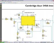
here is an example of a wellknown chipamp (sorry for the bad pic. quality).
(without input filter cap , paralell 22k/r58)
(without input filter cap , paralell 22k/r58)
Attachments
Last edited:
The schematic in post #32has a high pass corner frequency on the input that is lower than the corner frequency of the feedback network, an arrangement that can lead to trouble. I recommend the input Fc be at least three times (I usually shoot for ten times)the Fc of the feedbak for maximum stability.
Mike
Mike
The schematic in post #32has a high pass corner frequency on the input that is lower than the corner frequency of the feedback network, an arrangement that can lead to trouble. I recommend the input Fc be at least three times (I usually shoot for ten times)the Fc of the feedbak for maximum stability.
How can attenuating the input signal cause instability? Unless there's some wicked interaction between the inverting and non-inverting pins of the LM3886 (and I highly doubt that), anything on the input will have no impact on the stability. Only the components in the feedback loop and the load will impact small-signal stability. For large signal stability, you need to include the power supply decoupling and run the return paths for the large currents in a way that doesn't disturb the input ground.
~Tom
This is the best chipamp you can make -- the LM4780 is, of course, 2 LM3886's so just adopt for your purposes:
An externally hosted image should be here but it was not working when we last tested it.
Looks like Bob Cordell's circuit. I actually think you can improve it further by turning it into a composite amp. Then stability becomes a challenge, but it can be done...
~Tom
I actually think you can improve it further by turning it into a composite amp.
It still suffers from the LM3886's paltry 50dB PSRR at 20kHz so yes it can be improved substantially by addressing this. KSTR has shown a circuit which helps.
How can attenuating the input signal cause instability? Unless there's some wicked interaction between the inverting and non-inverting pins of the LM3886 (and I highly doubt that), anything on the input will have no impact on the stability. Only the components in the feedback loop and the load will impact small-signal stability. For large signal stability, you need to include the power supply decoupling and run the return paths for the large currents in a way that doesn't disturb the input ground.
I made no referance to attenuating the input signal. Think about what could happen if a lower frequency signal gets passed through to the input of the amp that the feedback network won't be able to handle due to it's higher roll off frequency, do you think there might be a potential problem with that?
This applies to all amps with global feedback that are not unity gain stable.
Mike
Last edited:
I made no referance to attenuating the input signal.
Not directly. However...
Let's call the LF cutoff (pole) frequency caused by the AC coupling cap and the input impedance f1. If it's just a simple RC on the input, f1 = 1/(2*pi*R*C).
Any input signal significantly higher in frequency than f1, say 10*f1, goes straight through, unattenuated. Any input signal significantly lower in frequency than f1, say f1/10, is attenuated. The filter slope is +20 dB/dec. Between f1/10 and 10*f10, the filter attenuation transitions smoothly from the +20 dB/dec slope to 0 dB/dec slope.
Now, let's look at the feedback network. The common resistor from OUT to IN- with a resistor in series with a capacitor from IN- to ground form a zero and a pole in the closed loop response of the amp. A zero will cause the slope of the gain curve to increase by 20 dB/dec. A pole will cause the slope of the gain curve to decrease by 20 dB/dec.
Think of it this way: At DC, the feedback cap to ground acts like an open circuit. This turns the amplifier into a buffer with a gain of 1. Mid band (i.e. where the closed loop gain has stabilized to the THX standard +26 dB) the feedback cap acts as a short circuit and you get Vout/Vin = 1+Rfeedback/Rground. Between DC and midband, the zero and pole in the closed loop response caused by the feedback network will cause the closed loop gain of the amp to rise smoothly from +1 to 1+Rfeedback/Rground, where it stabilizes.
Think about what could happen if a lower frequency signal gets passed through to the input of the amp that the feedback network won't be able to handle due to it's higher roll off frequency, do you think there might be a potential problem with that?
No I don't. The amp will handle those frequencies just fine. Recall the LM3886 has 115 dB of gain at DC... If you apply an input to the amp of 1 V DC or, say, 1 V RMS at 0.001 Hz, you'll get 1 V DC or 1 V RMS at 0.001 Hz due to the reason I described above.
If you're not convinced, I suggest you set it up in a circuit simulator. You can simulate the circuit with TINA-TI (free download from Analog, Embedded Processing, Semiconductor Company, Texas Instruments - TI.com). Or use any other Spice simulator and use a generic op-amp model.
This applies to all amps with global feedback that are not unity gain stable.
Unity gain stability has nothing to do with the input.
Instability is caused when the phase angle through the amplifier and the feedback network to the inverting input is greater than 180 º as this will cause positive feedback. If the loop gain (gain of the amp and the feedback network combined) is greater than 1 V/V when the phase hits -180º, the amp will oscillate. Of course you'll want some margin there so a slight change in component parameters won't cause instability. This margin is called phase margin (PM) and is (-180)-(phase angle of loop at the frequency where the loop gain hits 1 V/V). In textbooks, you'll find the general recommendation to be PM >= 45 º is considered stable. In the opamps I've designed, I've aimed for PM >= 60 º and you'll find many of the National Semiconductor amps are designed for that as well.
A unity gain stable opamp is an opamp that has sufficient PM to be stable even at unity gain. So basically, it's an opamp where the phase of the AVOL hits -120 º (or better) when the magnitude of the AVOL hits 1.
I hope this clears things up a bit...
For a more thorough but still relatively accessible text on opamps and feedback, I suggest looking at Sergio Franco, "Design With Operational Amplifiers and Analog Integrated Circuits", chapter 8.
~Tom
Last edited:
I respectfully disagree. Here's why. You mention that the chip has 115dB gain at DC, but I was talking about what happens to the amp's gain BELOW Fs on the feedback network where the amp's gain begins to fall off toward unity. For example, let's say you have a Lm3886 configured for DC coupling at the input and AC coupling with a Fc of 100Hz on the feedback network while running a gain of 10 for the pass band (an extreme case just to illustrate my point). What would happen if you applied a 20Hz signal to the input? At that frequency the gain would fall toward unity and the amp would be operating in an unstable conditon. So doesn't it seem appropriate to design the circuit in such a way to minimize the possability of causing the issue to begin with, especially since the fix is cheap and easy; just make the cap on the feedback network bigger.
Mike
Mike
- Status
- Not open for further replies.
- Home
- Amplifiers
- Chip Amps
- Improving the LM3886 amplifier