You don't want to know how long that took 😀.
I spend quite some time on it with just a jigsaw, a router and some templates... cutting took me about 3 months!
It was made using 2x 18 mm Baltic birch 2240 mm x 1220 mm pieces and one 15 mm 2240 x 1220 mm each speaker.
I made sure I could nest the 18 mm pieces to save material.

To bad it cracked on me... that's why I'm not done yet. It will be done but I'll have to wait for the spring to be able to continue.
I spend quite some time on it with just a jigsaw, a router and some templates... cutting took me about 3 months!
It was made using 2x 18 mm Baltic birch 2240 mm x 1220 mm pieces and one 15 mm 2240 x 1220 mm each speaker.
I made sure I could nest the 18 mm pieces to save material.
To bad it cracked on me... that's why I'm not done yet. It will be done but I'll have to wait for the spring to be able to continue.
I agree single driver Nautaloss I vs II is test to do. The turntable can be used if outdoors with no walls. Otherwise mic has to be moved around room. Like I said, the AkAbak sim already shows that the horizontal polar will be the same.
If you used a ribbon tweeter that was 7.5" tall (off the top of my head) would have the same effect.
If placed in a larger room, even if for nothing more than background, will exhibit a rising response at distance.
What! Cracked?! Do tell.
Looks like you did a good job using as much material as possible. At least it didn't come out like the Leaning and Crooked Tower of Pisa, like a friend of mine did. It really wasn't funny, at the time too much effort was put in. He bought some cheap ply off of a truck, supposed leftovers from a job... it was seconds. Thickness in width was off by a 1/16"! Every bloody board, glued, stacked and bolted through top to bottom. When we started evening up the slices we were getting all over the place. Full stop. Put the other together dry fit and bolted. What a wibbly mess, made a good bon fire. Of course 20 odd years l8r we laugh about it. Oh the trials and tribulations of speaker construction 😉
Looks like you did a good job using as much material as possible. At least it didn't come out like the Leaning and Crooked Tower of Pisa, like a friend of mine did. It really wasn't funny, at the time too much effort was put in. He bought some cheap ply off of a truck, supposed leftovers from a job... it was seconds. Thickness in width was off by a 1/16"! Every bloody board, glued, stacked and bolted through top to bottom. When we started evening up the slices we were getting all over the place. Full stop. Put the other together dry fit and bolted. What a wibbly mess, made a good bon fire. Of course 20 odd years l8r we laugh about it. Oh the trials and tribulations of speaker construction 😉
here's another material that would work excellant when lamentating sheets.
0 005" Unclad 360IN² FR4 PCB Insulator Insulating Sheet | eBay
I'm trying to find the supplier of the thicker glass boards I have. 12" x 24" 0.020 and 0.025 thickness used for RC jet construction. As this industry has flip flopped do to the economy don't know if the company is still around. Over in Lakeland FL. Near the airport, where Sun 'n Fun and RC Jets Show fly.
For that I point you to: http://www.diyaudio.com/forums/full-range/242171-making-two-towers-25-driver-full-range-line-array.html
Most of the story so far is there.
X, I do hope you'll be able to do the polar measurements...
I would satisfy my curiosity somewhat 😉, whatever the outcome...
Most of the story so far is there.
X, I do hope you'll be able to do the polar measurements...
I would satisfy my curiosity somewhat 😉, whatever the outcome...
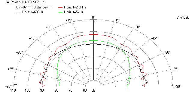
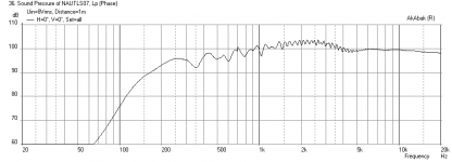
Sims of Polar Response of Nautaloss II
For Nautaloss II with dual drivers and single driver case. Speaker 45 in above floor and 40 in away from back wall. Mic is 1 m away with 8 volts rms drive. You can see the effect of the floor bounce causing ripples as well as the baffle step loss which causes a rising response ffrom 500 Hz to 2 kHz.
SPL vs Freq for Single Driver Case:

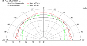
Polar Response for Single Driver Case (600 Hz, 2.5kHz, 5 kHz):
SPL vs Freq for Dual Driver Case:

Polar Response for Dual Driver Case (600 Hz, 2.5kHz, 5 kHz):
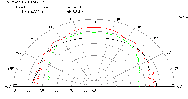
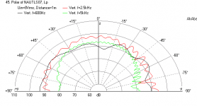
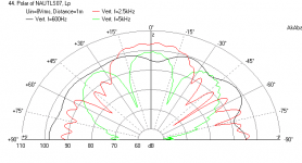
As you can see, the dual driver case does not change the horizontal polar response except for SPL level being higher. However, for the vertical polar response there is lobing at 5 kHz with the dual driver version as expected. Single driver vertical polar response:
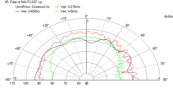
Dual driver vertical polar response:

For Nautaloss II with dual drivers and single driver case. Speaker 45 in above floor and 40 in away from back wall. Mic is 1 m away with 8 volts rms drive. You can see the effect of the floor bounce causing ripples as well as the baffle step loss which causes a rising response ffrom 500 Hz to 2 kHz.
SPL vs Freq for Single Driver Case:
Polar Response for Single Driver Case (600 Hz, 2.5kHz, 5 kHz):
SPL vs Freq for Dual Driver Case:
Polar Response for Dual Driver Case (600 Hz, 2.5kHz, 5 kHz):
As you can see, the dual driver case does not change the horizontal polar response except for SPL level being higher. However, for the vertical polar response there is lobing at 5 kHz with the dual driver version as expected. Single driver vertical polar response:
Dual driver vertical polar response:
Attachments
-
 Nautaloss-II-1-driver-FR-1m.png23.1 KB · Views: 831
 -
 Nautaloss-II-1-driver-1m.png16 KB · Views: 824
 -
 Nautaloss-II-2-drivers-FR-1m.png23.2 KB · Views: 823
 -
 Nautaloss-II-2-drivers-1m.png16.7 KB · Views: 827
 -
 Nautaloss-II-1-driver-1m-vertical.png16.5 KB · Views: 789
 -
 Nautaloss-II-2-drivers-1m-vertical.png18.6 KB · Views: 786
Last edited:
Excellent work. The dual TC9 version is clearly a 'sit down and stay put' speaker........and there's nothing wrong with that other than it looks bad on paper. In almost every measurement scenario, a single point source will have better polars than anything else.
In lies the problem with these little Fullrange drivers in that they're extremely SPL limited when used individually. But I bet your single driver version would be hard to beat in the nearfield. Impressive work all around.
In lies the problem with these little Fullrange drivers in that they're extremely SPL limited when used individually. But I bet your single driver version would be hard to beat in the nearfield. Impressive work all around.
Thanks, Mayhem13! These monitors do indeed work very well in nearfield and for most home listening.
Good work! One thing I am curious about is that ripple in the frequency response...
It looks a lot like this:

As the single driver Nautaloss show that as well it seems like baffle edge diffraction to me?
(the graphs above are a bit of an exaggeration but you get the idea)
At least there is the "proof" that the dual version does not alter the horizontal off axis plots. As stated before the test.
The vertical results were a given, but I do hope this clears up some of the statements made in this thread 😀.
In other words: no real surprises here! Thanks a lot for doing this X, hope it serves it's purpose.
It looks a lot like this:
As the single driver Nautaloss show that as well it seems like baffle edge diffraction to me?
(the graphs above are a bit of an exaggeration but you get the idea)
At least there is the "proof" that the dual version does not alter the horizontal off axis plots. As stated before the test.
The vertical results were a given, but I do hope this clears up some of the statements made in this thread 😀.
In other words: no real surprises here! Thanks a lot for doing this X, hope it serves it's purpose.
Last edited:
Wesayo,
You are welcome! I also just took polar data (0, 15, 30, 45, 60, 75, 90 deg). What a pain that was for both speakers. It will be a while before I can extract and put into polar plot but visually it looks all good - consistent with predictions. So no effect of dual drivers on horizontal polar response. I also took some measurements at 2 ft intervals around listening position to see effect of sweet spot with stereo operation. Measurments made at 1 m so I now have reference data and it confirms smooth response and off axis response fall off of Vifa. Dual drivers boosted efficiency by 6dB exactly as expected. I also listened to Nautaloss I again. They sound better for presentation of image overall - more coherent. Not surprising so I think for near field where you don't need louder levels, single driver is still best.
Regarding ripple, you are probably right about the enclosure maybe doing that. Your rounded edges will probably be better. There is ripple in the data for sure and maybe I will try a rounded front baffle made of XPS foam hand carved radiused?
Last edited:
About that ripple, it would be fun and not to hard to try right?
Still wondering about that more coherent sound of the Nautaloss I though... It will be true that the energy spread into the room (power response) of the I is better / more even than that of the nautaloss II. Would that make the difference? It is not the direct sound as presented in the measurements you made that makes the difference it seems. But it could very well be the lobes etc in reflection making the II less coherent?
Just trying to learn something from this test here. (and trying to make sure my arrays could very well be as coherent as that single driver)
Right, I was thinking of taping on some XPS foam round over edges on the baffle. It will make it wider though. Also easy enough to add thin piece of foam with offset baffle.
Regarding coherency - it may be the vertical lobing that puts incoherent reflections off the floor and ceiling and this does not show up in measurments. I have not looked at the phase yet. That may reveal something.
With two drivers this may well be less coherent but with a floor to ceiling 25 drivers it makes a magical change to being coherent again. The floor to ceiling span is important.
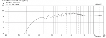
I was playing with EQ'ing the Nautaloss to achieve a perfectly flat response in-room and it measured well but things just sounded funny on some tracks - especially acoustic pieces in intimate settings mic'd for stereo imaging. I realized that all that EQ'ing was messing with the phase in the 500 Hz to 5 kHz range. I bypassed all the EQ'ing on the Nautaloss II tops (just left the LR XO between the tops and the subs) and the sound quality and imaging dramatically improved. Here is a measurement with no EQ applied and the phase varies smoothly and linearly rather than wrapping through 180 deg with each PEQ applied. There is still one phase wrap at the XO region but it is in a range that is not associated with spatial imaging. I like it better now and it reminds me the importance of having a good speaker to start with so you don't need to apply heavy EQ'ing. The mic was in between the 2 drivers and I think this was at a point that caused the falloff above 10 kHz. Farther away it would not have been an issue. Below 200 Hz is all the room modes going on, I am surprised to get bass down to 30 Hz.
Freq Response & Phase, Distortion, and Impulse Response.
xrk971 many thanks for sharing this thread, i have followed with big interest as an hoobyist diy.
About this perfectly flat response EQ'ing i have some input/idea. Is it possible for you to borrow somewhere friend/shop a Behringer DEQ2496. I say this because it has FIR linear phase filters (1x31graphic EQ+10xParametric used as/or high-cut/low -cut/shelving. This should heal the 180° phase wrapping, and then excited if that phenomena with some tracks sounded funny will disappear, and the overall sound picture will be even better than that you have now.
I have some of these units myself and it's very powerfull/good for the cost. Myself though have exchanged all the too cheap caps with good industry standard or better.
It would also be possible to do the trick below suggested, but you would need 2 times the unit + one more power amp.
..........A crossover part on one woofer will change the phase at that crossover point though, unless you use a fancy type of phase linear crossover.
Last edited:
Byrtt,
I am quite sure that 2496 uses IIR filters like the miniDSP - meaning it introduces phase errors with EQ'ing. It requires a very powerful Gflop floating point processor like a state of the art PC or Sharc DSP to do real time linear phase FIR filters. The level of DSP in the $350 Behringer cannot so this. If I am mistaken someone let me know and I will buy one even with its analog front/rear end issues.
I am quite sure that 2496 uses IIR filters like the miniDSP - meaning it introduces phase errors with EQ'ing. It requires a very powerful Gflop floating point processor like a state of the art PC or Sharc DSP to do real time linear phase FIR filters. The level of DSP in the $350 Behringer cannot so this. If I am mistaken someone let me know and I will buy one even with its analog front/rear end issues.
The effect will exhibit an increasing issue as frequencies rise above 3380. One plot at 5k isn't enough information to show the differences. Doing a vertical plot would significantly show the effect, which may or may not help depending on your listening requirements, room, etc.
Otherwise thank you for what you've shown. Yes it is a PITA. Only need to do 0° - 90° on one side of one speaker unless the drivers are offset on the baffle eg asymmetrical. Measuring both speakers from 90°- 0° - 90° isn't necessary in your case. Well unless your looking for differences between the two speakers 😉
Comb filter effect is not an issue with line arrays, but is at it's worst with 2 drivers. One driver is a simple point source, which would be optimum if we could get the required spl's out of them.
I'm so over the you have to sit exactly here, X, to hear it the way it's ment to be heard. When I stand up do not want to hear a shift in spectrum and lastly when I walk through a room I do not want to hear any funky squishy phasiness in the top end. Wesayso's line array will not exhibit these issues, yours will and why this more critical than you may think.
I do think the Vifa drivers for anything listening but nearfield do need two (or more) drivers to get adaquate listening volume. That Naut speaker does have enough room in the front part of the spiral to angle up or even mount the second speaker on the top. You might get internal reflections with this config. Might have to try it. Will use the first Naut I've built for this test since the box is already glue spattered.
I'm so over the you have to sit exactly here, X, to hear it the way it's ment to be heard. When I stand up do not want to hear a shift in spectrum and lastly when I walk through a room I do not want to hear any funky squishy phasiness in the top end. Wesayso's line array will not exhibit these issues, yours will and why this more critical than you may think.
That's why I like listening in my car with DSP power.... your head is pretty much always in the same position, with a little work (actually a lot of work) you can get great results that even allow you to move around a bit.
I'm building the arrays in hope to get similar imaging as I experience in my car, where you totally forget the speaker positions (can't tell where they are by listening) and listen only to the music. But with a bigger sweet spot.
A solution like the synergy from Tom Danley is intriguing as well, acting as close to a point source as possible. It does however still have some minor problems of its own for HiFi, or so it seems.
Last edited:
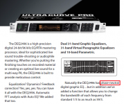
Checked their web and they now call it phase neutral (newer website), on the old website i for sure have seen they mentioned words like "FIR" and "linear phase". I attach a screen capture from a newer PDF brochure.Byrtt,
I am quite sure that 2496 uses IIR filters like the miniDSP - meaning it introduces phase errors with EQ'ing. It requires a very powerful Gflop floating point processor like a state of the art PC or Sharc DSP to do real time linear phase FIR filters. The level of DSP in the $350 Behringer cannot so this. If I am mistaken someone let me know and I will buy one even with its analog front/rear end issues.
In my 3 oldest units there is 2 times Sharc DSP Analog Devices ADSP-21065L + one Triscend A7S a SoC with 32-bit RISC CPU. Having one newer unit where those devices are the newer followers released by the brands.
Do we have some free software that measure the phase behave truly, i can do some desktop soundcard loop'ing thru DEQ2496 with and without EQ'ing or HP or LP filters to reveal the phase behavour.
You mention "analog front/rear end issues", do you mean the high levels +12dBu/22dBu, else one can use the digital I/O both available as SPDIF coxial and toslink.
Attachments
Last edited:
Byrtt,
I don't know what "phase neutral" means but if they don't say FIR, it's not because that is a big deal. The 2496 is indeed feature packed and I think quite nice. I have heard from several folks that the quality of the analog circuitry is not good - Bob Richards shows how to diy fix it yourself but looks involved. The issues are not the high levels but poor analog design (I think, lack of dynamic headroom and noise?).
For measurement, you can't beat REW - it is free and totally feature packed. It has a calibration feature where you can look at what your electronics are doing. As always, a loopback cable will let you check your electronics and if it introduces phase errors.
You can also check by putting a single full range driver connected and apply a PEQ right in the middle of the bandwidth like 5kHz. Should be flat there but if you do and record with a mic in nearfield you will see a phase distortion.
It will probably show up with loopback test too.
Thanks xrk971.
I will find time tomorrow looking at REW, and try do some test.
I actual run fullranger Alpair 10.2M daily so this could be usefull to your suggestion, and also the loop I will try.
I am actual curious myself to get it revealed, because now for some years i have ran DEQ2496 daily and give me a perception of linear phase. Therefor if this test shows it wraps phase, i have some sound perception in my brain to be updated. But I think it's FIR linear phase because compared to same EQ done by my analog EQ units it sounds different.
About the analog I/O at least the output is simple cheap to fix because of the SPDIF I/O feature directly into digital CPU power, at HiFimeDIY Store find some nice ES9023 equipped DAC's at nice costs and minimal labour.
- Home
- Loudspeakers
- Full Range
- The Nautaloss Ref Monitor