Small typographical correction to the formula expression: 1 ÷ 44.1kHz ÷ 2^16; ÷ 2 = 173 (ps)
Yeh but what does this mean? Why we divide one period by 65535? That will correspond to 2.9Ghz frequency - something far beyond audio domain.
I understand low jitter for clock - that makes sense, but
does it really matter how precisely we will push data word into DAC's input latch? Data jitter should be very enormous to cause any error there..
The issue with jitter in digital audio rarely has to to do with actual bit transmission error. As you indicate, even hundreds of nano-seconds of jitter won't induce a bit error in a CD audio chain. It has to do with modulation of the domain (A/D or D/A) conversion instants. Jitter is a modulation in time phenomena. A jitter figure such as 173ps represents an amplitude in time, not a period in time equating to a 2.9GHz frequency. So, jitter with 173ps time amplitude could have a jitter frequency of only a few hertz, or anywhere within the audio band. Such time modulation of the conversion instants manifests in a digital audio chain as signal amplitude errors - digital signal amplitude errors upon A/D conversion, and analog signal amplitude errors upon D/A conversion. Jitter can produce inter-modulation like spectral lines and noise at audio frequencies in the analog output signal.
My own take on what the Kusunoki formula tells us is, that it computes the maximum jitter amplitude before 1 LSB of effective system resolution is erased by that jitter.
Last edited:
The issue with jitter in digital audio rarely has to to do with actual bit transmission error.
...
My own take on what the Kusunoki formula tells us is, that it computes the maximum jitter amplitude before 1 LSB of effective system resolution is erased by that jitter.
Yeh i understand about main clock jitter. It does make audio difference. I just don't understand about WS/data jitter and why it is so important to reclock when DAC has internal latch which will kill any DATA W/S jitter right away. I only raise this question because i dont hear audio difference because it is either irrelevant or i've done something wrong. WHatever you say is generic to any jitter in general and does not say why we should have that reclock and why reclock riming parameters are so strict.
Hi a1j,
kusunoki
...
This is one of the reasons I abandoned the TDA1541A for now while thinking about possible fixes for this difficult issue.
...
Thanks for detailed explanation.
What is your DAC of choice then right now?
Is there any new thread about Ultimate DAC V.2?
Yeh i understand about main clock jitter. It does make audio difference. I just don't understand about WS/data jitter and why it is so important to reclock when DAC has internal latch which will kill any DATA W/S jitter right away. I only raise this question because i dont hear audio difference because it is either irrelevant or i've done something wrong. WHatever you say is generic to any jitter in general and does not say why we should have that reclock and why reclock riming parameters are so strict.
Although the latching of input data data is determined by the word-clock signal, the data conversion instant is not necessarily determined by word-clock. In the 18-bit AD1865, the word-clock signal serves as the conversion instant strobe. In the 24-bit PCM1704, bit-clock serves as the conversion strobe. While in low-bit high-oversampling Sigma-Delta DAC chips, the conversion instant is determined by the system-clock signal. In all cases, the critical signal for jitter is the one controlling the actual data conversion instant. The input latch is simply a holding place for time aligning the data to the clock signal controlling the data conversion instant. Deriving a sufficiently jitter free local clock signal, especially at 'close-in' frequencies, from an asynchronously recovered remote clock signal is non-trivial.
Last edited:
Hey guys, this thread should be going strong! It´s one of the best sources of information in this site. And the products developed by John are at the highest level. In fact John, I would like to speak to you in private about buying the SD-player. From all we talked, I believe you have one of the very best sources available.
Cheers
-Alex
Cheers
-Alex
I agree, i am listening to his player for two months now, i'm amazed that 16 bit 44 khz can sound that analog, it sounds like vinyl only cleaner and more detaild, i think my search for a analog digital medium has ended with this player
Best analog digital medium ever heard
I am listening to this player for to months now , and can finally say my search for a analog digital medium has ended with this player.
Never believed that 16 bit 44khz could sound that analog, it sounds like vinyl only cleaner and more detailed, with a great musicality , an extreme recognition of the instruments as they sound.
Dont chase after hires material, with this player you have music with 44 khz 16 bit
Hi, Shinja
I tried this method. It really works. Optimum bias voltage was +(60-65) mV. Especially strongly reduced 2nd harmonic. Other harmonics are reduced, too, though to a lesser extent.
This tweak may make worse chip to be better performance...
I tried this method. It really works. Optimum bias voltage was +(60-65) mV. Especially strongly reduced 2nd harmonic. Other harmonics are reduced, too, though to a lesser extent.
[ ] The input latch is simply a holding place for time aligning the data to the clock signal controlling the data conversion instant. Deriving a sufficiently jitter free local clock signal, especially at 'close-in' frequencies, from an asynchronously recovered remote clock signal is non-trivial.
I have the problem on non-locking at higher frequencies from an XMOS card; TDA1541 works good on SAA7220 output; but not good on XMOS card at 176 kHz. I don't know what the reason is (which line, BCK or WS) is at fault, just it does not lock at higher frequencies. I suspect the PS of the card I use to be bad, as the signal deteriorates after some time.

I have the problem on non-locking at higher frequencies from an XMOS card; TDA1541 works good on SAA7220 output; but not good on XMOS card at 176 kHz. I don't know what the reason is (which line, BCK or WS) is at fault, just it does not lock at higher frequencies. I suspect the PS of the card I use to be bad, as the signal deteriorates after some time.
I've not experimented with XMOS card, nor the TDA1541. In addition, I'm uncertain what you mean by, "non-locking" problem. That said, however, the first thing I suggest you do is to verify that the XMOS card's output signal is set to I2S format. Once you are positively certain that's not the trouble, the next thing I would do is to verify the quality of the three I2S signals (bitclock, wordclock, and data). Each should meet the datasheet timing requirements of the TDA1541, and be properly time alignment with respect to each other. For 176kHz sample rate signals, you will likely need an 200MHz, or quite possibly higher, bandwidth oscilloscope to verify the timing.
Last edited:
Correction: For 176kHz sample rate I2S signals, you will likely need about an 50MHz oscilloscope, 100MHz would be better, to verify the timing.
The TDA1541 have a max bclk spec of 6.4Mhz with normal 64fs frames you are exceeding that above 96khz.
The SAA7220 uses 172khz with 32bit frames. hence only 44.1*4*32 = 5.6Mhz bclk
The SAA7220 uses 172khz with 32bit frames. hence only 44.1*4*32 = 5.6Mhz bclk
The TDA1541 have a max bclk spec of 6.4Mhz with normal 64fs frames you are exceeding that above 96khz.
The SAA7220 uses 172khz with 32bit frames. hence only 44.1*4*32 = 5.6Mhz bclk
Agreed. My TDA1541a works great with WaveIO up to 96khz. just noise beyond.
Agreed. My TDA1541a works great with WaveIO up to 96khz. just noise beyond.
Same here with WaveIO...
BUT....😕 .....Ian have pushed it to 196Khz
http://www.diyaudio.com/forums/digi...d-post3462438.html?highlight=1541#post3462438
Same here with WaveIO...
BUT....😕 .....Ian have pushed it to 196Khz
http://www.diyaudio.com/forums/digi...d-post3462438.html?highlight=1541#post3462438
Tazzz has identified the reason why some have been able to run the TDA1541 at a 176KHz sample rate, while others have not. The reason is that the TDA1541 can accept a 32-bits per frame multiplexed (2-channel) data input, while most all other DAC chips of which I'm aware only accept a 64-bits per frame multiplexed data input. This means that for a given sample rate, the TDA1541's data and bitclock input signals run at half the frequency which they would need to for another DAC chip.
Therefore, as Tazzz shows in post #4973, a 176kHz sample rate digital signal with a 64-bit frame size features data and bitclock signals which are higher in frequency than are supported by the TDA1541.
I've not experimented with XMOS card, nor the TDA1541. In addition, I'm uncertain what you mean by, "non-locking" problem. That said, however, the first thing I suggest you do is to verify that the XMOS card's output signal is set to I2S format. Once you are positively certain that's not the trouble, the next thing I would do is to verify the quality of the three I2S signals (bitclock, wordclock, and data). Each should meet the datasheet timing requirements of the TDA1541, and be properly time alignment with respect to each other. For 176kHz sample rate signals, you will likely need an 200MHz, or quite possibly higher, bandwidth oscilloscope to verify the timing.
Ken,
What I have is that the output can work good [for some time] into TDA1543; while the TDA1541 starts to distort.
After a few minutes the signal will distort. It takes about 3 minutes to reach that stage.
The following pictures are all 176Khz. At 44, 48, 88 and 96 there is a good signal.
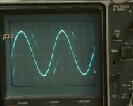
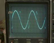
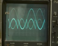
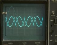
I called it 'non-locking' but it might have better diagnosis.
I only hav 10 mHz so can't do any analysis.
My hypothesis: i think the power supply converter on the XMOS board (5v--> 3,3,V) starts to fail.
What i can also see on the scope is that the BCK is superimposed on the WS. [But have no picture yet of that].
at 96 kHz the output is OK, see the picture of both channels:
I implies the I2S is OK, but there is some kind of synch losing out, or some other strange behavior....🙁
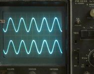
Il'd be so happy with some clue where to look...
albert
...Il'd be so happy with some clue where to look...
albert
Hi, Albert,
As I've stated, I've not experimented with the TDA1541, nor the XMOS card. However, the first thing I suggest is that you determine the frequency of the bit-clock input signal (BCK) on pin-2. As 'Tazzz' points out, the maximum acceptable frequency here is 6.4MHz. Your 10MHz scope will still allow you to view this signal, although it will probably appear quite rounded and sinewave-like. That's okay, you merely want to know what the frequency is.
I would expect a correct bit clock frequency to be about 5.6MHz, given a 176kHz sample rate multiplexed audio signal. If the frequency seems to be higher than 6.4MHz, that is a problem. I should think this would be due to the XMOS card output format not being correct for the TDA1541's needs. In other words, it may be that the XMOS card does not support the multiplexed 32-bits per frame required by the TDA1541. Check the relevant XMOS documentation for this mode. By the way, the reason things seem to work for short while and then quit, may simply be a thermal generated side-effect from applying too high of a bit-clock and data signal frequencies.
Remote troubleshooting, such as this, is often highly error prone due to misinterpretations and faulty assumptions on my part about what exactly you are seeing at your end. Keep reporting what you find, and I'll continue trying to help.
Last edited:
498 page too long
sory now i have TDA1541 & CS8414
can you up layout for TDA1541. power use LM317,337 or 7915, 7805,7905
sory now i have TDA1541 & CS8414
can you up layout for TDA1541. power use LM317,337 or 7915, 7805,7905
Z600,
this is a particular thread about ECDESIGN DAC,
for your question look at Raindrop'hui commercial DACS for basics design like the one you talk about. Her PCB (Hui is a woman i read somewhere) are good for playing with personal tunning. Just IMHO. And I am very happy with one of her pcb AD1865 with my own tuning.
I can understand your sadness : that's about TDA 1541 and now it's not anymore (because too bad, because genuine aviability, ?) but John give us many many things to improve or do our pcb or set up.
Sad we don't know the name of the new DAC chip, but maybe the TDA 1543 or 1545 or the one used by our fellow german friend of AMR ????
Last edited:
- Home
- Source & Line
- Digital Line Level
- Building the ultimate NOS DAC using TDA1541A