I use proper copper rods on my dedicated circuits (though one has cable TV and web connection) and balanced power transformer, which is not exactly isolation transformer.
I like balanced power 🙂
Cheers,
M.
I like balanced power 🙂
Cheers,
M.
hi ecdesigns,
could you tell me how i would be able to float pin 7 of 1543 if i was using active i/v stage such as zen or ad844?
and is there any other trick that can be performed for the pair of 1543 in balanced config with flipflopped data?
thank you.
i've been toying with 1543 since the beginning of this year and your pin float mod still stands as the most dramatic improvement to the chip, yet. i also was regarding your i2s signal attenuation circuit with diode strings but found out that it was reducing the gain in a balanced config where the data signal is fed through 74hc04 hex inverter.
when i disconnect the diode string the gain would go up.
Could you drive a copper rod into your soil ? Mine would look like a pretzel....I need the copper clad steel.
These grounds improved the TV cable reception....
These grounds improved the TV cable reception....
I use proper copper rods on my dedicated circuits (though one has cable TV and web connection) and balanced power transformer, which is not exactly isolation transformer.
I like balanced power 🙂
Cheers,
M.
Let me make a guess: PCM56 😀
It can't be connected to I2S, can it? 🙄
It can't be connected to I2S, can it? 🙄
Use I2S for what ?
Hi, Shinja
Interestingly, you yourself have used this method? Can you tell me what are the results?
This is not entirely true. You can create a constant bias voltage across the I/U resistor.
This tweak may make worse chip to be better performance, or typical chip to catch S2 spec, I expect.
Interestingly, you yourself have used this method? Can you tell me what are the results?
This tweak is unsuitable for passive IV circuit.
This is not entirely true. You can create a constant bias voltage across the I/U resistor.
I use proper copper rods on my dedicated circuits (though one has cable TV and web connection) and balanced power transformer, which is not exactly isolation transformer.
I like balanced power 🙂
Cheers,
M.
Hi,
Whats the difference between that and a iso transformer?
I use a EMI common mode mains filter for my dac and it definitely makes a difference for the better. It´s a delta electronics, sealed can, I took it from a no-break.
I have been browsing this thread, looking for ideas to improve my dac, and something struck me here: the dedication and diligence of John and how much he has given here.
John: Your work is much appreciated! This thread is invaluable for any serious diyer.

Best regards,
Alex
John: Your work is much appreciated! This thread is invaluable for any serious diyer.
Best regards,
Alex
Last edited:
Hi,
Whats the difference between that and a iso transformer?
I use a EMI common mode mains filter for my dac and it definitely makes a difference for the better. It´s a delta electronics, sealed can, I took it from a no-break.
Hi. These guys explain it better than I could:
Index of Technical Articles About Balanced Power
John: Your work is much appreciated! This thread is invaluable for any serious diyer.
Yes, his approach is like analysing with a magnifying lens every step of the chain and he has shown that every single part of his low parts count DACs matters to audio...
Cheers,
M.
Thanks, I have to check that out.
Do you connect the safety earth to the ground of your circuits? I don´t. I only connect the earth to the emi filter. From there I take only the two power wires to the trafo.
My dac is a tda1543 (selected chips), lm7808 reg, 1K passive I/V , tent clock, optical spdif i/o (sends clock to the computer for sync). Presently it´s cap coupled directly to a gainclone, gain of 10, and I attenuate a few db digitally in J.River. It´s sounding better than ever!
The speakers are small tannoy mx2-m and I enjoy the music a lot.
Cheers,
Alex
Last edited:
Hi maxlorenz,
Are these big enough?
THE BIGGEST HORN SUB OF THE WORLD by Roberto Delle Curti ITALY
Or some for listening outside:
Desibel, the world’s largest mobile horn system | Maja Solveig Kjelstrup Ratkje
When it has to be a bit louder:
World's loudest speaker - Was 3000 by Wyle labs
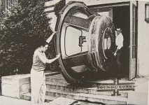
Attached picture shows practical problems that can be encountered when building larger (horn) speakers.
"Thou shall build big horn speakers"
Are these big enough?
THE BIGGEST HORN SUB OF THE WORLD by Roberto Delle Curti ITALY
Or some for listening outside:
Desibel, the world’s largest mobile horn system | Maja Solveig Kjelstrup Ratkje
When it has to be a bit louder:
World's loudest speaker - Was 3000 by Wyle labs
Attached picture shows practical problems that can be encountered when building larger (horn) speakers.
Attachments
Hi maxlorenz,
Are these big enough?
THE BIGGEST HORN SUB OF THE WORLD by Roberto Delle Curti ITALY
Or some for listening outside:
Desibel, the world’s largest mobile horn system | Maja Solveig Kjelstrup Ratkje
When it has to be a bit louder:
World's loudest speaker - Was 3000 by Wyle labs
Attached picture shows practical problems that can be encountered when building larger (horn) speakers.
That's for his car. You should see the ones for his house speakers. 😱
Hi maxlorenz,
Are these big enough?
THE BIGGEST HORN SUB OF THE WORLD by Roberto Delle Curti ITALY
Or some for listening outside:
Desibel, the world’s largest mobile horn system | Maja Solveig Kjelstrup Ratkje
When it has to be a bit louder:
World's loudest speaker - Was 3000 by Wyle labs
Attached picture shows practical problems that can be encountered when building larger (horn) speakers.
Thanks for the link, dear -EC-.
It proves that a high WAF is sine qua non in this hobby. 😀
Not my kind of installment, thou...I think the front pannel for the 8 woofers on the Italian SW is weak. 🙁
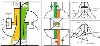
I attached a diagram of my last project which will use an Audio Nirvana Super 10 which has resonance at 31Hz...
Fortunately, I like to listen my music (mainly dead people's music) at low or medium volume, most of the time.
BTW, on my big Autograph videos, it was the "scrambler-interpolator DAC" that was playing. Last night we had a big party but I failed to induce distortions in my system 😀
Dear Alexandre,
Sorry for the late reply...try to find alternative to the voltage reg which will most probably bring significant improvement to the sound.
I use my DIY version of this one:
SuperTeddyReg | DIY | TeddyPardo
SuperTeddyReg | Resources | TeddyPardo
Good luck.
M.
Attachments
Last edited:
Thanks Maxlorenz and John
That regulator is definitely on my list, as are a number of Johns circuits and ideas. I do believe he has the very best player as far as time resolution is concerned. And, as far as i know, our hearing is most sensitive to the time information!
Best regards
Alex
That regulator is definitely on my list, as are a number of Johns circuits and ideas. I do believe he has the very best player as far as time resolution is concerned. And, as far as i know, our hearing is most sensitive to the time information!
Best regards
Alex
Last edited:
....
Here are calculated max! jitter levels for 44.1/16 NOS with indicated resolution:
44.1/16 NOS, 0.1 LSB (15.5 bit resolution), 1 / (44,100 * 1) / (2^16 / (1 / 0.5)) = 173ps.
44.1/16 NOS, 0.1 LSB (15.9 bit resolution), 1 / (44,100 * 1) / (2^16 / (1 / 0.1)) = 34.6ps.
44.1/16 NOS, 0.01 LSB (15.99 bit resolution),1 / (44,100 * 1) / (2^16 / (1 / 0.01)) = 3.46ps.
....
Balanced, high amplitude masterclock with less than 1ps jitter (requires no comparator), SN74AUC1G74 with typical 3.5ps jitter, so total jitter equals approx. 4.5ps for BCK timing.
hm datasheet on that chip
http://www.ti.com/litv/sces537d
shows that propagation delay is 2.5ns (not 3.5 ps) - that's almost 1000 times difference.
More to that i cannot find any triggers on mouser that have propagation delay lower than 200ps. in fact 1/3.5ps is about 286GHZ !!! Which is far beyond consumer electronics domain.
Please explain.... i'm confused. How those femtoseconds numbers got calculated?
Now here's my calculation:
Lets imagine triangle wave with 45 degrees slope, DAC has 1% error between 2 adjacent levels of signal.
To match that precision clock should have jitter of 1% from 1/44kHz which is
0.268 microseconds. !!!
Lets do 8x oversampling....
Ok divide that number by 8... Still very far from femtoseconds...
EDIT: in reality 1% is probably far fetched. 50% will be sufficient for 15.5 bit DAC. which means multiply jitter numbers by 50.
Last edited:
Hi aj,
Jitter is not equal to propagation delay. This ECL divider for example has 320ps propagation delay and specified typical 0.2ps random jitter:
http://www.onsemi.com/pub_link/Collateral/MC10EP33-D.PDF
This boils down to a difference between propagation delay and random jitter of 320 / 0.2 = 1600
shows that propagation delay is 2.5ns (not 3.5 ps) - that's almost 1000 times difference.
Jitter is not equal to propagation delay. This ECL divider for example has 320ps propagation delay and specified typical 0.2ps random jitter:
http://www.onsemi.com/pub_link/Collateral/MC10EP33-D.PDF
This boils down to a difference between propagation delay and random jitter of 320 / 0.2 = 1600
Hi aj,
Jitter is not equal to propagation delay. This ECL divider for example has 320ps propagation delay and specified typical 0.2ps random jitter:
http://www.onsemi.com/pub_link/Collateral/MC10EP33-D.PDF
This boils down to a difference between propagation delay and random jitter of 320 / 0.2 = 1600
Thanks for the link and explanation. Could you also explain how required jitter numbers got calculated? I have modified my cd player with
1. New clock - significant audible improvement
2. new decoupling caps in 1541A - significant audible improvement
3. DEM clock (half frequency of main clock) - audible cracking noise on low sound levels is gone
4. Reclock (74 series flipflop) - NO audible change.
I'm now trying to decide if i have done something incorrectly (wrong triggers perhaps) or jitter figures exaggerated or audible difference is not as big as in case with 1. and 2. Thanks!
Hi a1j,
kusunoki
1 ÷ 44.1kHz ÷ 216; ÷ 2 = 173 (ps)
Based on extenive (listening) tests and feedback from audiophiles it still makes sense to attempt to get jitter levels as close to zero as possible. In other words it would be best to obtain zero jitter as non-zero jitter levels do cause audible degrading on sets capable of providing high resolution.
Audio sets with low resolution and recordings that don't drive the playback system to its limits may not reveal the impact of very low sample timing jitter levels as distortion caused by jitter is masked.
Downsampling and or lower smple rates reduce the audible effect of sample timing fluctuations. Up / oversampling and higher sample rates increase the audible effect of sample timing fluctuations.
When sample timing fluctuations become audible they exceed audibility threshold of roughly 1%. Most DACs have no problem maintaining low THD that is much lower than the audible impact of sample timing fluctuations.
So in my humble opinion, tackling jitter should always have highest priority as it causes highest audible distortion by far.
By using 44.1/16 NOS we have two advantages. First the impact of given A/D conversion jitter is reduced by higher downsampling factor (to 44.1 KHz). Second, by keeping sample rate as low as possible, the impact of given playback clock jitter is also minimised by maximising sample duration.
It is already extremely difficult to minimise audible degrading caused by A/D and D/A conversion jitter in a DAC that is least sensitive to jitter.
Audio set resolution is limited under practical listening conditions due to ambient noise, room acoustics and volume setting for example. Under these practical conditions one is unable to hear 16 bit resolution, in practice this would be more like 8 … 10 bits.
One would have to listen in an Anechoic Chamber to possibly hear some more bits of a 16 bit converter at top volume setting. One's own heartbeat, streaming of the blood and breathing would still mask LSBs of a 16 bit system. One migt just be able to hear 12 … 14 bits under these conditions. Listening to music in such a chamber isn't pleasant so this isn't a solution to resolve the lowest bits. Listening at top volume level is also not practical.
1. Masterclock jitter amplitude and spectrum can easily change perceived sound, however a change in sound isn't always an improvement. The effects of jitter can be very misleading.
2. When TDA1541A DEM clock frequency is around 200 KHz (typical), active divider decoupling has to meet requirements of RF decoupling. This requires minimising of stray inductance. This can be obtained by using shortest possible PCB traces, suitable ground planes and small size decoupling caps with lowest possible stray inductance. On top of all this the decoupling caps need to have lowest possible DC leakage current and should not suffer from piezoelectric effects like from X7R or Y5V ceramic caps for example. I ended up using 1uF 1210 size SMD film caps mounted underneath the TDA1541A.
There are indications that TDA1541A DEM circuit prevents ultimate performance due to on-chip crosstalk and resulting jitter spectrum. Even when the active divider outputs were perfectly decoupled, this on-chip crosstalk issue remains. This is one of the reasons I abandoned the TDA1541A for now while thinking about possible fixes for this difficult issue.
3. Audible (low level) distortion with the TDA1541A is a result of a DEM circuit that is not working at all or is not working correctly. The clock frequency should have no effect on this. DEM clock source has direct impact on crosstalk with I2S signals. DEM clock rates within the audio spectrum become audible as idle tones, this also proves the crosstalk issue. Synchronising the DEM clock on multiples of fs can reduce audibility of on-chip crosstalk but it is extremely difficult to synchronise the DEM oscillator while maintaining extreme low jitter on timing signals and minimising noise injection through the synchroniser circuit. Possible solution may be the use of an ECL injector circuit (800mVpp output signal and very low jitter contribution).
4. I can be short on (CMOS) reclocking, it doesn't provide best results. Stray capacitance between all pins of a logic building block like a D flip-flop for example prevents full jitter blocking. In other words, some amount of jitter will always manage to seep through a (synchronous) reclocker. It basically means that one cannot fully remove jitter from a jittery source by reclocking its output signals.
So I switched to the clean source concept where I don't have to block source jitter and thus eliminate all issues related to reclocking. This clean source concept also eliminates all (jitter) issues related to external DACs.
Thanks for the link and explanation. Could you also explain how required jitter numbers got calculated?
kusunoki
1 ÷ 44.1kHz ÷ 216; ÷ 2 = 173 (ps)
Based on extenive (listening) tests and feedback from audiophiles it still makes sense to attempt to get jitter levels as close to zero as possible. In other words it would be best to obtain zero jitter as non-zero jitter levels do cause audible degrading on sets capable of providing high resolution.
Audio sets with low resolution and recordings that don't drive the playback system to its limits may not reveal the impact of very low sample timing jitter levels as distortion caused by jitter is masked.
Downsampling and or lower smple rates reduce the audible effect of sample timing fluctuations. Up / oversampling and higher sample rates increase the audible effect of sample timing fluctuations.
When sample timing fluctuations become audible they exceed audibility threshold of roughly 1%. Most DACs have no problem maintaining low THD that is much lower than the audible impact of sample timing fluctuations.
So in my humble opinion, tackling jitter should always have highest priority as it causes highest audible distortion by far.
By using 44.1/16 NOS we have two advantages. First the impact of given A/D conversion jitter is reduced by higher downsampling factor (to 44.1 KHz). Second, by keeping sample rate as low as possible, the impact of given playback clock jitter is also minimised by maximising sample duration.
It is already extremely difficult to minimise audible degrading caused by A/D and D/A conversion jitter in a DAC that is least sensitive to jitter.
Audio set resolution is limited under practical listening conditions due to ambient noise, room acoustics and volume setting for example. Under these practical conditions one is unable to hear 16 bit resolution, in practice this would be more like 8 … 10 bits.
One would have to listen in an Anechoic Chamber to possibly hear some more bits of a 16 bit converter at top volume setting. One's own heartbeat, streaming of the blood and breathing would still mask LSBs of a 16 bit system. One migt just be able to hear 12 … 14 bits under these conditions. Listening to music in such a chamber isn't pleasant so this isn't a solution to resolve the lowest bits. Listening at top volume level is also not practical.
1. Masterclock jitter amplitude and spectrum can easily change perceived sound, however a change in sound isn't always an improvement. The effects of jitter can be very misleading.
2. When TDA1541A DEM clock frequency is around 200 KHz (typical), active divider decoupling has to meet requirements of RF decoupling. This requires minimising of stray inductance. This can be obtained by using shortest possible PCB traces, suitable ground planes and small size decoupling caps with lowest possible stray inductance. On top of all this the decoupling caps need to have lowest possible DC leakage current and should not suffer from piezoelectric effects like from X7R or Y5V ceramic caps for example. I ended up using 1uF 1210 size SMD film caps mounted underneath the TDA1541A.
There are indications that TDA1541A DEM circuit prevents ultimate performance due to on-chip crosstalk and resulting jitter spectrum. Even when the active divider outputs were perfectly decoupled, this on-chip crosstalk issue remains. This is one of the reasons I abandoned the TDA1541A for now while thinking about possible fixes for this difficult issue.
3. Audible (low level) distortion with the TDA1541A is a result of a DEM circuit that is not working at all or is not working correctly. The clock frequency should have no effect on this. DEM clock source has direct impact on crosstalk with I2S signals. DEM clock rates within the audio spectrum become audible as idle tones, this also proves the crosstalk issue. Synchronising the DEM clock on multiples of fs can reduce audibility of on-chip crosstalk but it is extremely difficult to synchronise the DEM oscillator while maintaining extreme low jitter on timing signals and minimising noise injection through the synchroniser circuit. Possible solution may be the use of an ECL injector circuit (800mVpp output signal and very low jitter contribution).
4. I can be short on (CMOS) reclocking, it doesn't provide best results. Stray capacitance between all pins of a logic building block like a D flip-flop for example prevents full jitter blocking. In other words, some amount of jitter will always manage to seep through a (synchronous) reclocker. It basically means that one cannot fully remove jitter from a jittery source by reclocking its output signals.
So I switched to the clean source concept where I don't have to block source jitter and thus eliminate all issues related to reclocking. This clean source concept also eliminates all (jitter) issues related to external DACs.
- Home
- Source & Line
- Digital Line Level
- Building the ultimate NOS DAC using TDA1541A