- Because if you don't risk, you will never improve or initiate nothing.
Correct. Some of us just want to learn from mistakes made by others hehe
It is not this, Jay. Please think about the following:Yes, this argument again.
Just because you have used noisy DAC, it doesn't mean you can use noisy amplifier.
Apart some rare classical recordings, done with two mikes strait in the mastering machine, the only 'transparent' reproduction system for a given record is the one witch was used during mixing session. As dirty as it was.
It is not this, Jay. Please think about the following:
Apart some rare classical recordings, done with two mikes strait in the mastering machine, the only 'transparent' reproduction system for a given record is the one witch was used during mixing session. As dirty as it was.
I still don't understand the point. I mean, why every time I said I don't want opamp chip in my amplifiers, people come to say that my recordings have gone hundreds of opamps.?? I only say what I experienced with my ears, nothing to do with how records are made.
May be those opamps who are actually responsible with the "digital sound"?
A record is an artwork. If you want to reproduce a painting as the painter wanted-it to be, better use the exact same colors.I still don't understand the point.
I know what is tape and vinyl 'analog' sound: Heavy noises and distortions, changes in response curves etc....May be those opamps who are actually responsible with the "digital sound"?
I dont know what is 'digital' sound, when nobody, including musicians, in a good studio is able to make the difference between direct from an analog mixing desk and after tape (hundred time verified). Or so little changes, compared with all the other evils (bad instruments, acoustic problems, etc...)
Don't take this as an aggression, we, sound engineers have a different approach than audiophiles, as we are involved in all the industrial process of music production. Far from an ideal dreamed world or fairy tales.
But in deep concern with transparency (or neutrality) of the studios monitoring systems, as the accuracy of our work depend on it.
Even if some (not all!) recordings went through tens of opamps, any single one added to the playback chain changes the sound again and adds its own sound signature. Many of us were successful in ABX tests and had positive results in direct x opamp path comparison.
RNMarsh
Simple has a lot to offer. have you built it, yet?
This amplifier I didn't maid, but with same output stage the amplifier has been working for over 20 years and sounds great. As a driver it uses symmetric difcaskad with cascode VAS.
RNMarsh
Only the actual built circuit's performance is what eventually counts. So, I am hoping all designs that look promising in SIM as CFA contenders get a chance to be measured and listened to as the final test.
Yes, you're right. The final decision in favor of one or the other decision can be taken only by the results of listening.
I wrote earlier that my friend (former sound engineer, sound musical groups) worked on research causes affecting the quality of sound reproduction. As a result of numerous experiments involving musicians and specialists in the field of audio engineering, he came to the conclusion that the overall NFB adversely affect the sound. Therefore, in their designs refused to use common NFB.
At the last time he used as a voltage amplifier SRPP tube stage and as the output stage of the amplifier output stage Lamm M1.2. At the same time he was looking for a solution to the transistor equivalent sound quality tube amp voltage. Before we met he has achieved good results when using the voltage amplifier from the same CFA proposed ostripper. But this decision it is not completely satisfied with, as yet inferior to the tube stage. I offered him a check as a voltage amplifier cascode broken, which was only 4 transistor against the 12 of CFA. First he took my suggestion was very skeptical. But when he did a comparative listening with experts, it was found that it provides a more natural sound.
Moreover it turned out that in the broken cascode also desirable or acceptable NFB very little depth .
At the next stage, I asked him to improve the output stage using corrector Hawksford for negative output resistance minus 0.3 ohms. When he fulfilled all my recommendations he got the sound he dreamed all his life.
In this distortion likely path in the audio range does not exceed 0.05% without feedback .
For over a year he regularly conducts comparative blind listening tests your amplifier with the best brands and regularly its amplifier is the winner.
best regards
Petr
😎🙂
Yes, stay and be a part of it's history making discoveries in CFA (OK so I exaggerate); Great group over here and we want all the good design input and debate there is to have here.... all in one place for the DIY'ers who are reading and who will be reading in the future. But, if it is just the construction/build/PCB/BOM part of a design, that would be better served IMO in another thread.
Thx-Richard Marsh
Good point, Richard. The construction, PCB, etc portions of a design could get lost in a big, fast-moving thread like this.
The issues about CFA theory and the hard questions about CFA vs VFA should stay here. I also hope there will be less sniping, while at the same time honest difficult questions and challenges to assertions will not be received in a defensive way. For knowledge to spread in an understandable way, we must be able to drill down and distill the essence of the CFA.
Cheers,
Bob
Thanks guys .
I did start the thread. "SLEWMASTER" CFA vs. VFA "rumble".
I'll post on both threads , mainly design for this one and
"build" for the other one.
I've been digging in to Mr. Hawksford's papers , he is akin
to Tesla for audio amplifier design.
His cascode is amazing when combined with some of the better
VFA/CFA input stages. 😱
Design is ALL compromise ! "Try to get the most with the least"
Lazy cats "VSSA" is also a very good match for the
cascode. Adding a widlar to the cascode also has merit ....
I'm working on these "additions".
I really did not try to "shove" the cascode and triple down
everyone's throat (threadjack ?) , but they do have the lowest distortion vs.
complexity. My goal is to have a similar parts count/cost/complexity
as the "Badger" .... I have had little problem coaching error free
builds from that project despite the wide variations in sourcing.
I have a feeling my "next round" will even exceed this ...
I'm still "mentally visualizing the electrons " (Hawksford said this, too 😀)
OS
Hi OS,
I'm glad you'll continue to post here. I usually have a store of "Devil's advocate" questions to ask to help improve my own understanding, and perhaps hopefully that of others. I also usually have a store of "dumb" questions to ask. I believe that if you turn over enough stones you will eventually find a worm.
As far as Triples and cascodes, I don't see you as shoving them down anybody's throats. If so, I am guilty as well. I am a great believer in Triple output stages, be they Locanthi T circuits or other. I first discovered the great advantage of the cascode VAS when I designed my MOSFET power amplifier (it was a conventional cascode with a fixed bias on the cascode base). I have since learned that the added value of a cascode depends a lot on the type of main VAS transistor and also upon whether the VAS has an EF in front of it (what I have called a Darlington VAS, even though it is not technically so).
Cheers,
Bob
By the way, who can be here in a better position to explore what we can expect adding an error corection OPS to a CFA than you, if you have some free time left ?The issues about CFA theory and the hard questions about CFA vs VFA should stay here. I also hope there will be less sniping, while at the same time honest difficult questions and challenges to assertions will not be received in a defensive way. For knowledge to spread in an understandable way, we must be able to drill down and distill the essence of the CFA.
Indeed. less input parasitic capacitance (increase the slew rate), more linearity, more rail voltage... where are the cons ?I first discovered the great advantage of the cascode VAS when I designed my MOSFET power amplifier
Last edited:
I believe at lot in trying to separate voltages from currents, so if you by using a modulated cascode the current out sees a fixed voltage and thus the device capacitance is close to eliminated.
Also in the input-stage a hawksford cascode is very very good, especially when your current signal is modulated over a rail-resistor. If you look instead into a current mirror the hawksford cascode is not so significant, as the voltage is not so heavily modulated and thus the device capacitance of the input-pair is of lesser role.
Also in the input-stage a hawksford cascode is very very good, especially when your current signal is modulated over a rail-resistor. If you look instead into a current mirror the hawksford cascode is not so significant, as the voltage is not so heavily modulated and thus the device capacitance of the input-pair is of lesser role.
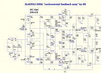
VSSA - Hawksford
Another contender for the "rumble" ....
Also a solid performer , lose the bloody diamond - get slightly
lower distortion.
But .... while being fast , not quite as fast as the "slewmaster" (NX-hawksford).
It compensates nearly as easily with simple MC. On
this round of simulations , I COULD NOT run without
compensation this time with the hawksford.
I saw why on my bode plot - the hawksford has its own pole (5-6mhz) , as it
is a local FB loop in itself.
In conclusion ... it's all compromise ,much better performance - slightly
harder to compensate.
Next - cascode the VSSA and/or add a mirror to the hawksford.
PS - also , I'm still reading hawksford's papers - I will attempt to
"tune" the cascode itself.
OS
Attachments

Now you have one of my test circuits, apart from the housekeeping and servo..🙂
I am now from your inspiration trying to get a robust servo working by injecting offset into the hawksford cascode, one problem seems to be the fact that the LED diodes i have used are too steep in the characteristics, so you need a lot of current to move it the needed amount.
With lower values in the feedback network you can improve the slew-rate. I use 22 ohme and 1mF to GND
Last edited:
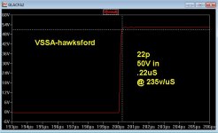
Nothing I do to the VSSA can make for 400-500v/uS.
Except....drive the input pair "direct". The diamond is
the key , it drives the CF pair "direct" in the NX and
buffers that pair from the higher impedance input.
So , the diamond (NX) makes for speed + a Hi imp. input.
 Excellent design decision , Bonsai !!
PS - I would build vssa-hawksford as well - could we
really tell the difference between 200 or 400v/us or
9 and 11 ppm - audibly ?
OS
Except....drive the input pair "direct". The diamond is
the key , it drives the CF pair "direct" in the NX and
buffers that pair from the higher impedance input.
So , the diamond (NX) makes for speed + a Hi imp. input.
Excellent design decision , Bonsai !!PS - I would build vssa-hawksford as well - could we
really tell the difference between 200 or 400v/us or
9 and 11 ppm - audibly ?
OS
Now you have one of my test circuits, apart from the housekeeping and servo..🙂
I am now from your inspiration trying to get a robust servo working by injecting offset into the hawksford cascode, one problem seems to be the fact that the LED diodes i have used are too steep in the characteristics, so you need a lot of current to move it the needed amount.
With lower values in the feedback network you can improve the slew-rate. I use 22 ohme and 1mF to GND
Yes , lowering Fb network R increased slew to 300+ v/us .
But , changed UG/phase margin. Increased MC to 47-56p to
regain my desired stability ... which , in turn "slowed" me down , again.
Also from the real world design standpoint ... that's a lot more current
passing through those caps to ultimately end up in the "clean star" 🙁 .
Buffering the CF pair still seems superior.
OS
By the way, who can be here in a better position to explore what we can expect adding an error corection OPS to a CFA than you, if you have some free time left ?
Indeed. less input parasitic capacitance (increase the slew rate), more linearity, more rail voltage... where are the cons ?
The cons with the cascode are fairly minimal. First, I don't mind the extra transistor in the signal path or the few cents associated with it or its base-biasing arrangement.
The cascode can in some situations introduce a bit more of a stability challenge, especially in a Miller-compensated 2-transistor VAS. The possibility of high-frequency instability in any of our arrangements is something we must always be very aware of. Who knows how many amplifiers out there may have their sound quality under some conditions affected by an unknown and fleeting parasitic oscillation. I have learned to look at almost every node in a simulation out to 100MHz in ac and also intransient to see if there is any tendency to very high frequency instability. Of course, that does not cover the additional possible tendencies to oscillation that crop up in the real world due to parasitics.
Another minor price of the cascode is some loss of VAS headroom.
The Hawksford cascode is slightly more prone to instability than a conventional cascode because it does involve some positive feedback.
Cheers,
Bob
The cons with the cascode are fairly minimal. 1. -First, I don't mind the extra transistor in the signal path or the few cents associated with it or its base-biasing arrangement.
2 .-Another minor price of the cascode is some loss of VAS headroom.
3. -The Hawksford cascode is slightly more prone to instability than a conventional cascode because it does involve some positive feedback.
Cheers,
Bob
1 . $.21 x 2 at mouser ...
2 . 3.1V per rail .... higher or boosted rail.
3. Decouple the cascode reference (diode string/leds) with .68u to 2.2u .
The dip and peak I experienced at 3-6mhz nearly disappeared and I
was able to run my previously posted amp w / NO compensation.
10pF was enough for more than 650v/us slew with minimal ringing.
15-22pf now will give 400V slew w/ no ringing. UG went slightly higher with
the caps. (one of the hawksford papers illustrated the caps - I tried them)
I most likely will not run this amp "full throttle" like this (33-47p is safe),
but having an even greater stability margin is nice.
OS
.....I
was able to run my previously posted amp w / NO compensation.
10pF was enough for more than 650v/us slew with minimal ringing.
OS
😎🙂 Check.
This is one of the big plus'es for CFA, IMO. I have never had to tweak compensation in my own symmetrical CFA design. When you want to put some more margin in, its simple and easy to do. Others here have also made this discovery. More confirmation, in my mind, why I like these CFA type designs. (rah rah rah).
Thx-RNMarsh
Last edited:
Is this real life or sim OS?
I do not get past 1.2MHz in real life. Only if i lower VAS gain!
I do not get past 1.2MHz in real life. Only if i lower VAS gain!
Here are three CFA "dumb questions/observations" that have probably been brought up here before, but not seen by me.
1. The Williamson tube amplifier and most others had the negative feedback connected to the cathode of the input stage. Does this make it a CFA?
2. The early solid state amplifiers had the negative feedback connected to the emitter of the fist-stage transistor. Did this make them CFAs?
3. I prefer solid state amplifiers with JFET input stages. I have not seen any CFAs here with JFET inputs. Are JFET inputs not compatible with CFAs?
I ask these questions in the spirit of the broader view of what is a CFA in this thread, as opposed to the more narrow technical definition that has sometimes been cited here.
Cheers,
Bob
I have pointed out before that circuit theory types usually don't make fine distinction between SE N or P, complementary, bjt or fet - there are common design rules for gbw, compensation despite "implementation details" http://www.diyaudio.com/forums/solid-state/240712-cfa-topology-audio-amplifiers-195.html#post3699867
Richard and others do seem to want to restrict their definition to not be as inclusive
Richard and others do seem to want to restrict their definition to not be as inclusive
Last edited:
- Home
- Amplifiers
- Solid State
- CFA Topology Audio Amplifiers